IDE Project 7: Modular Robotic Platform
A Robotic Platform made for Endless Possibilities.
This project was a challenge to myself: “Could I design, build, code and test my own robot?”. Following the Robotic Minor I have wondered this and believed I could manage this. The IPD master course Making and Prototyping Skills allowed an opportunity for a project of our own choosing.
I took this opportunity to develop a modular robotic platform based on a Raspberry Pi 5 for various possible expansions over the course of 2 months. This project challenged my skills in mechanics, mechatronics, CAD, 3D printing, coding electrical engineering.
As this project was executed in 4 rounds of two weeks during the course, this page will present the process in a similar fashion to show the development timeline accurately.
Round 1: Requirements and Mechanical Design
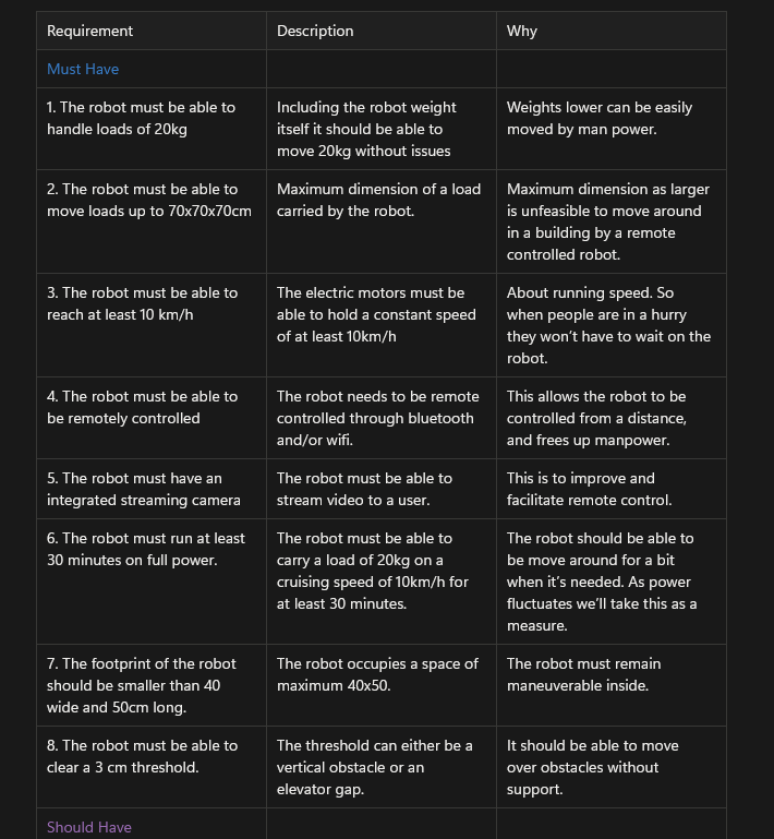
It starts with framing the design challenge. For this I used the MoSCoW method for determining requirements for the robot. Key requirements are the load capacity, control and modularity.
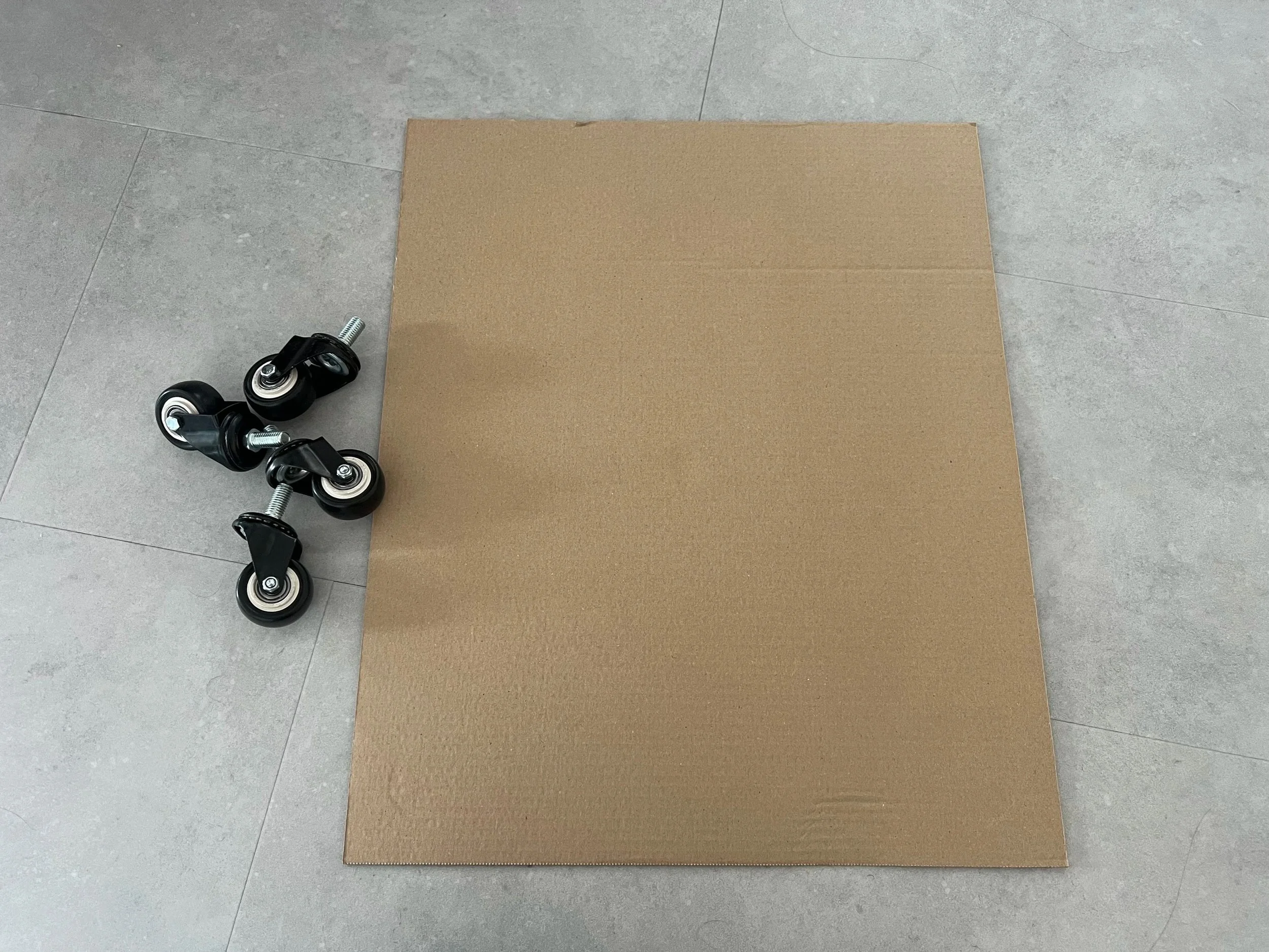
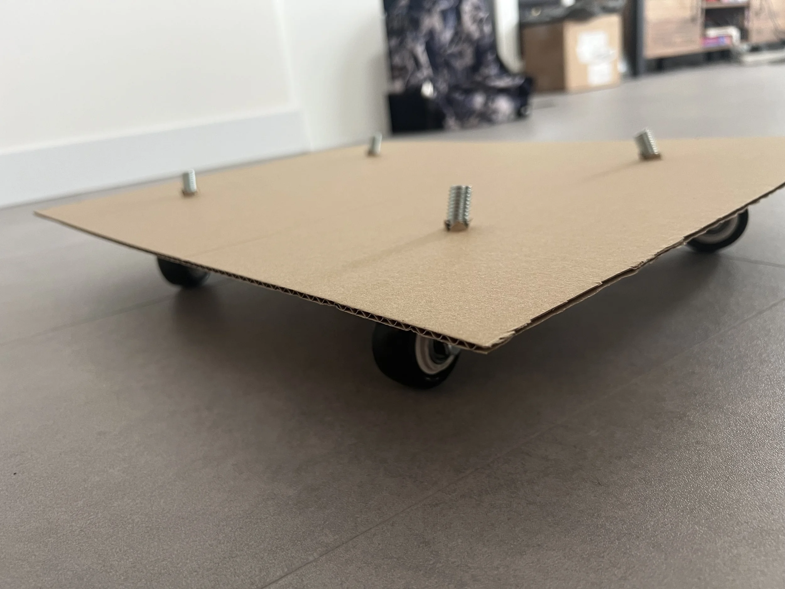
To quickly validate the robot requirements a quick prototype was created to move around the intended surroundings.
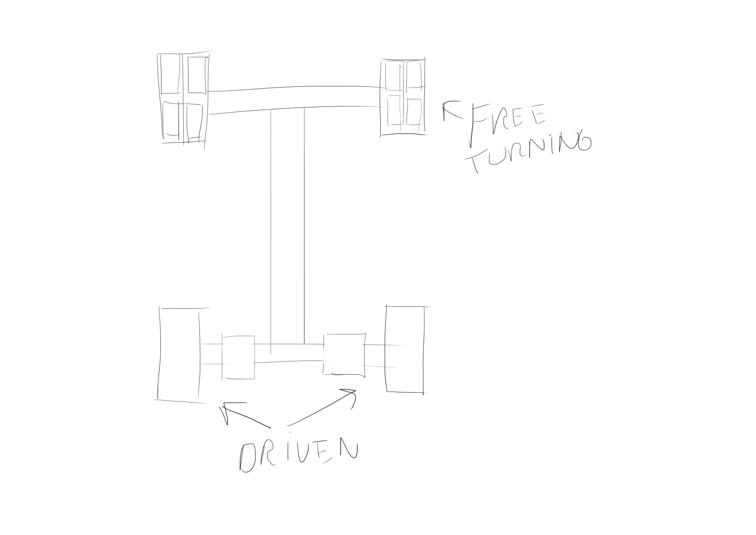
The next step involved determining the drive system of the platform, which was to be a pushbot configuration with 2 driven wheels and 2 omniwheels as castor wheels.
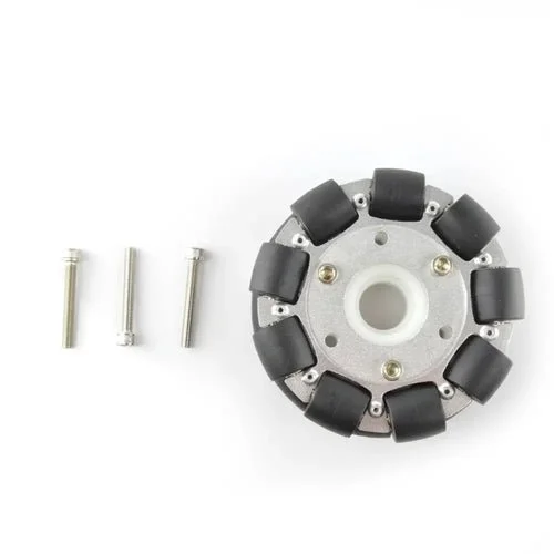
The omniwheels chosen were 100mm aluminum to be able to carry the loads required.
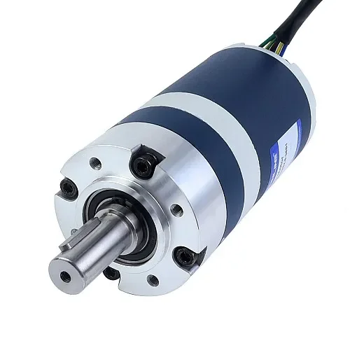
Using the speed, obstacle and load requirements a suitable 3.1Nm motor was chosen with a safety factor of 1.5.
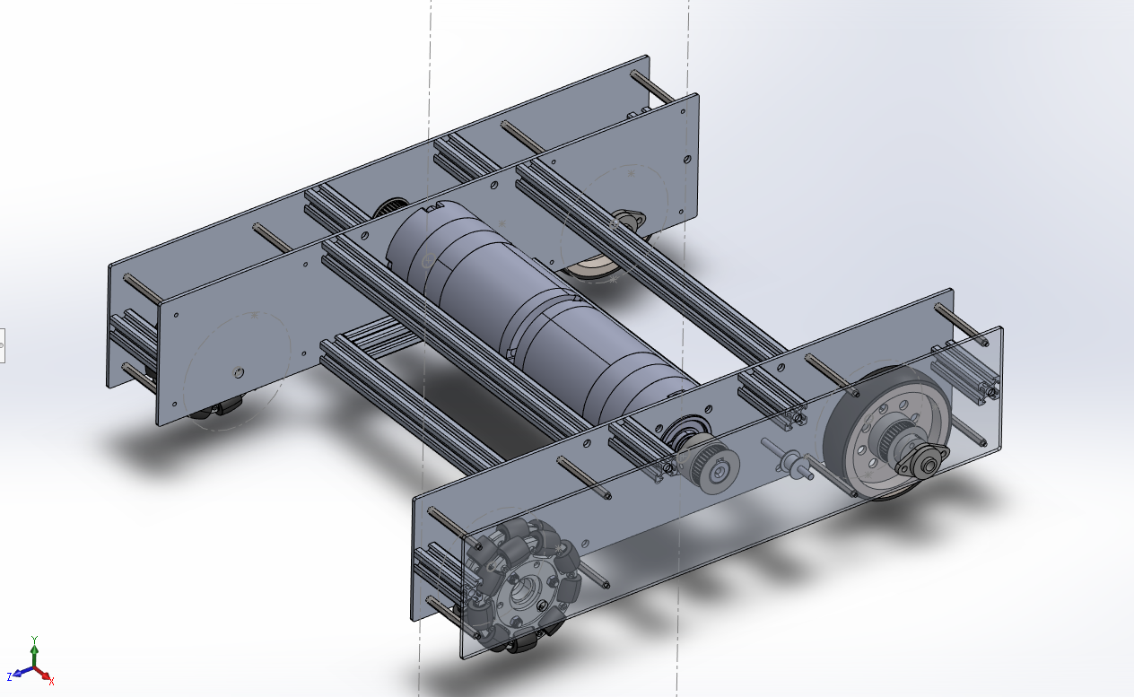
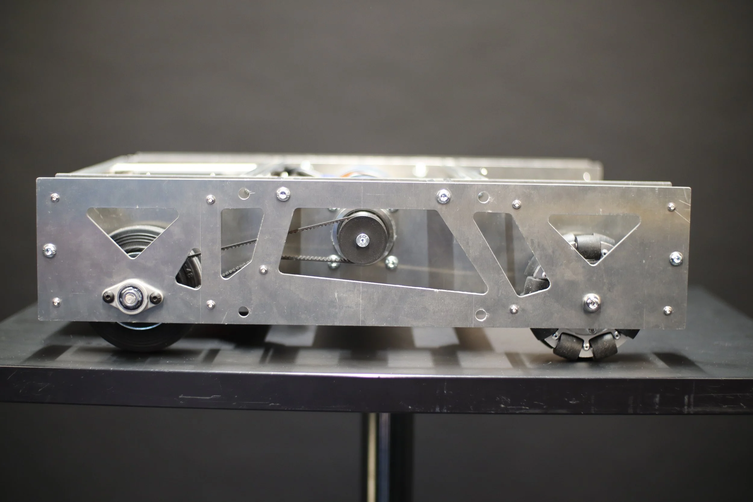
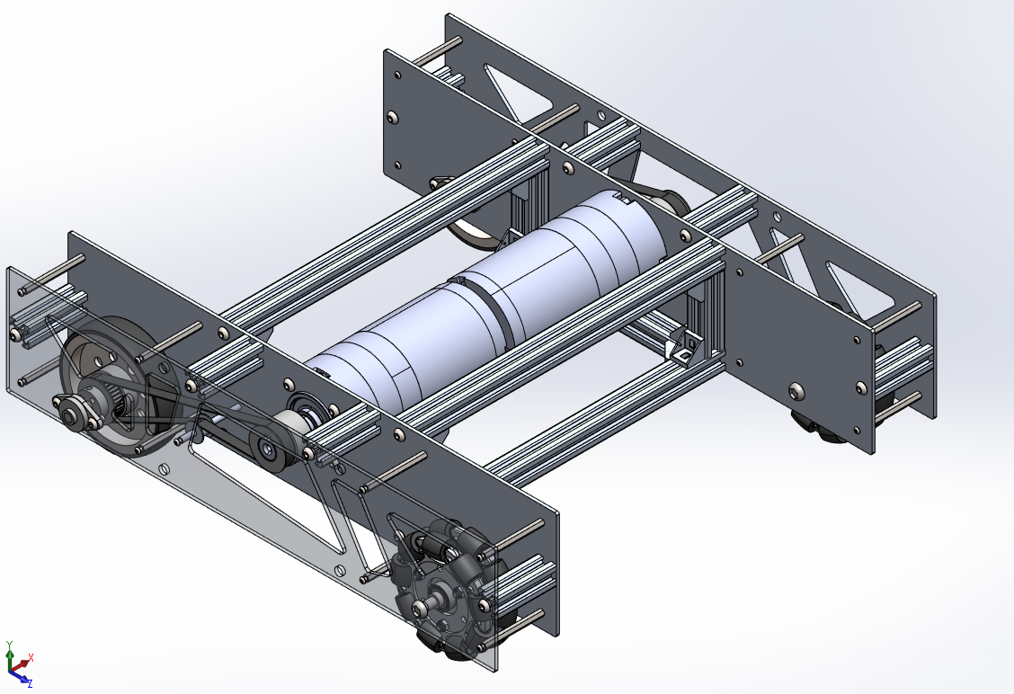
Using SolidWorks CAD software the robotic platform with the drive system was created. featuring a belt drive system using M3 high torque toothed belts and a tensioning system.
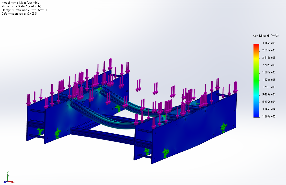
The drive platform was tested using SolidWorks Finite Element Analysis. These tests determined that the frame was far stronger than required.
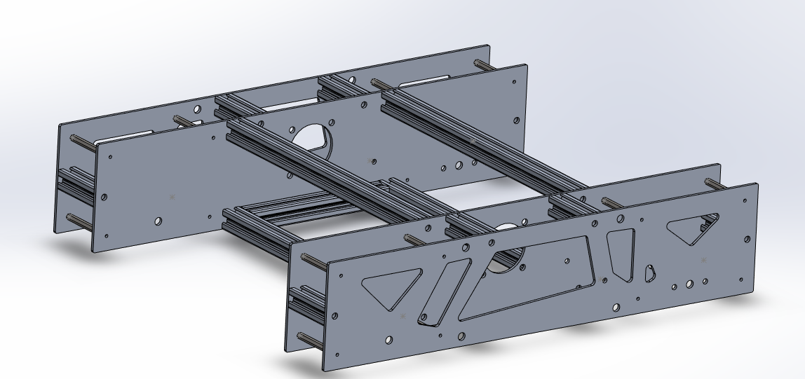
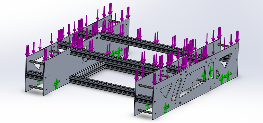
The frame was retested with the Pocketing technique applied and proved satisfactory.
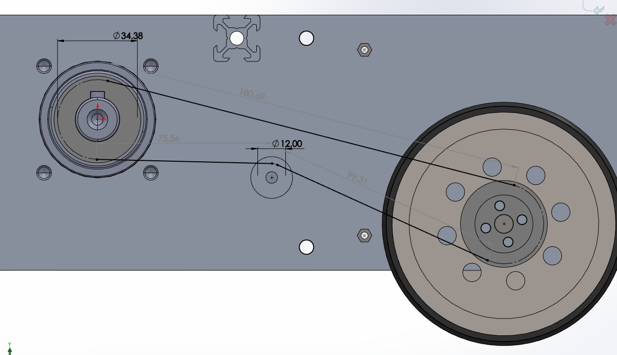
Finally, to finalize the bill of materials, the correct belt sizes were determined using the SolidWorks CAD assembly.

The drive platform design was now finished and ready for parts acquisition and manufacture.
Round 2: Manufacture, Control and Electronics
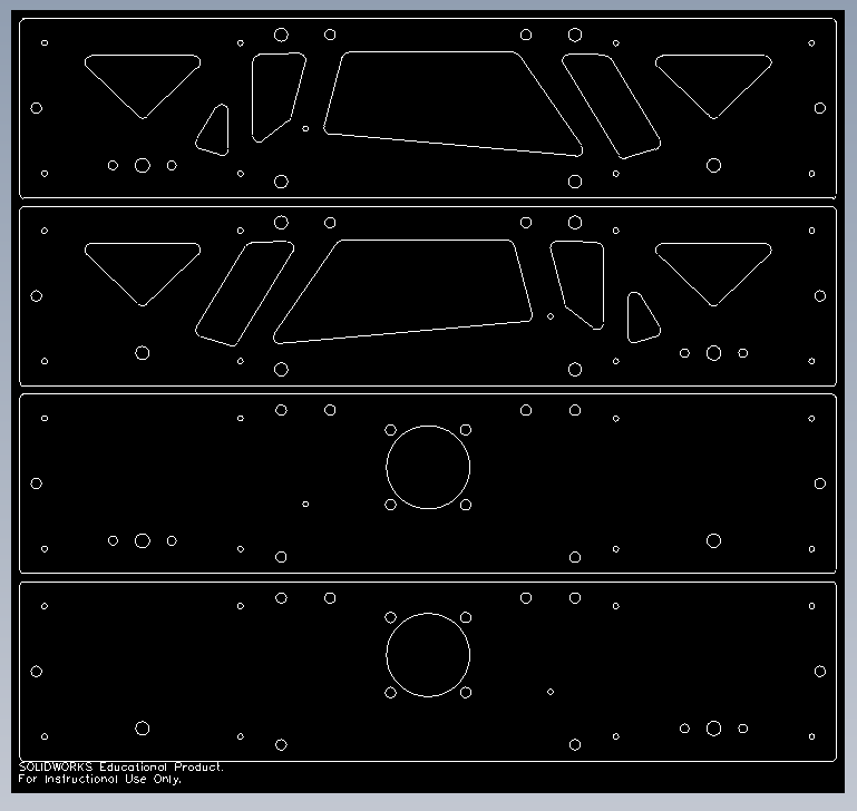
Using the SolidWorks Assembly, a BOM was created and laser-cutting files were produced for manufacture.
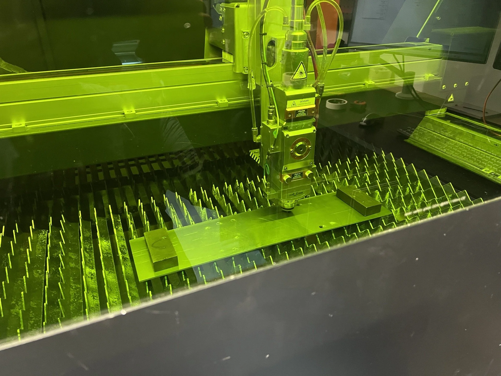
The drive walls were chosen to be 3mm laser cut aluminum walls.
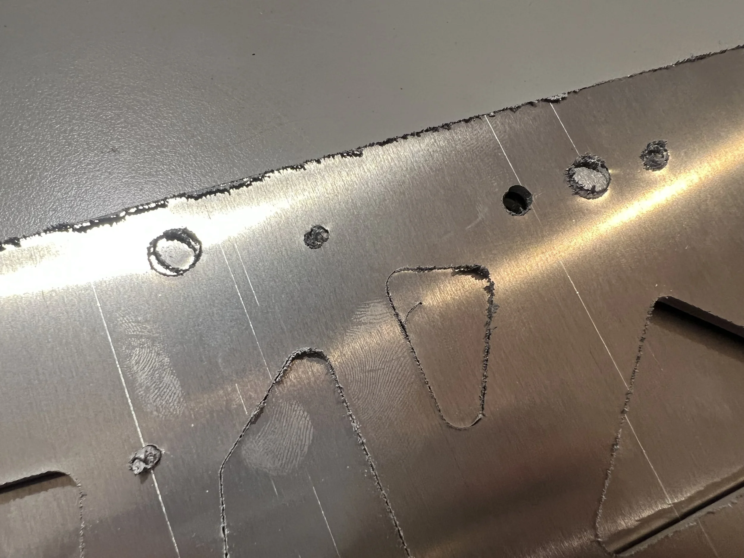
Some of the initial drive walls had manufacturing errors, however the defect walls could be re-cut quickly.
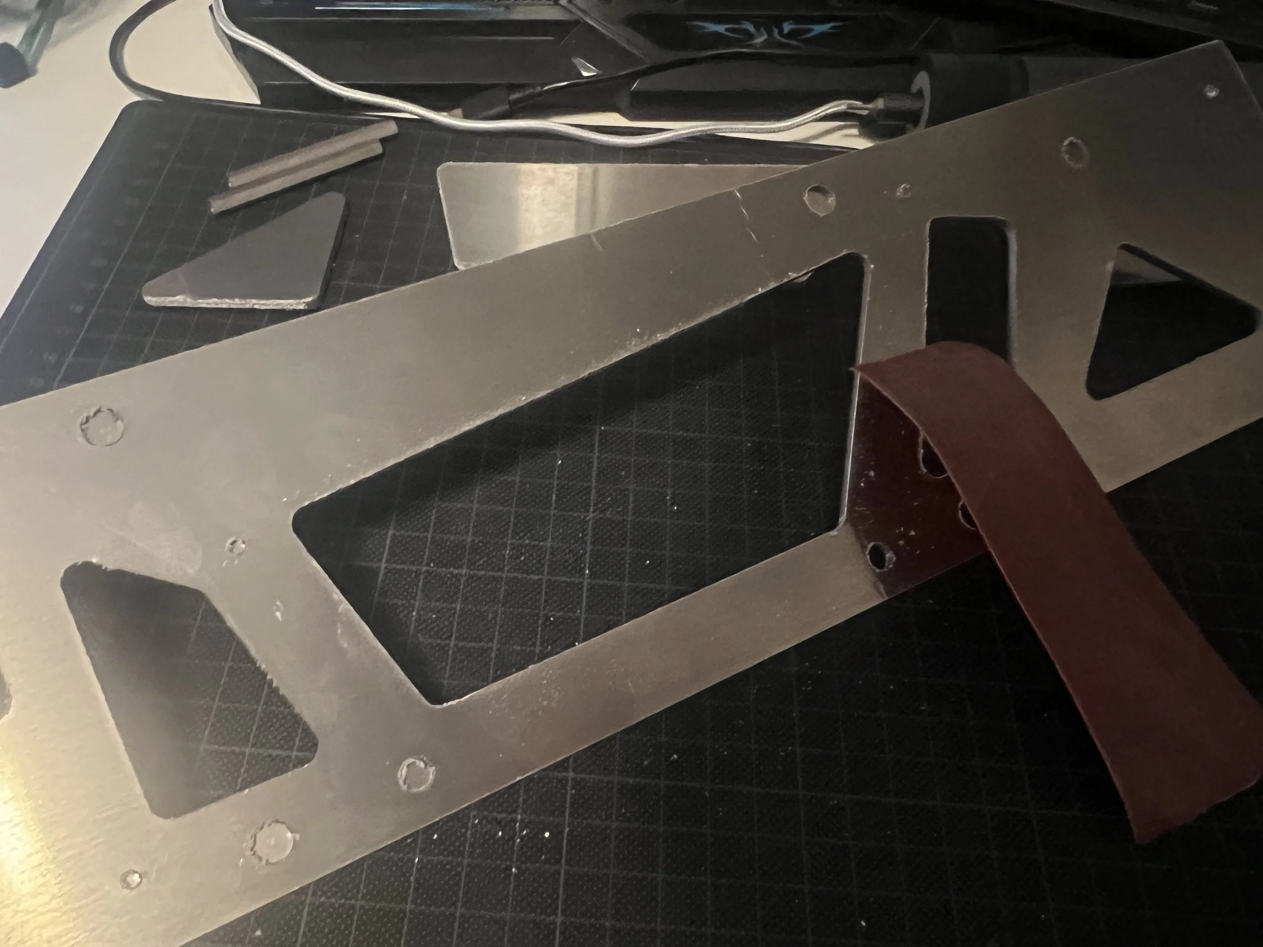
The aluminum material choice required some post-processing due to the aluminum spattering during laser-cutting.
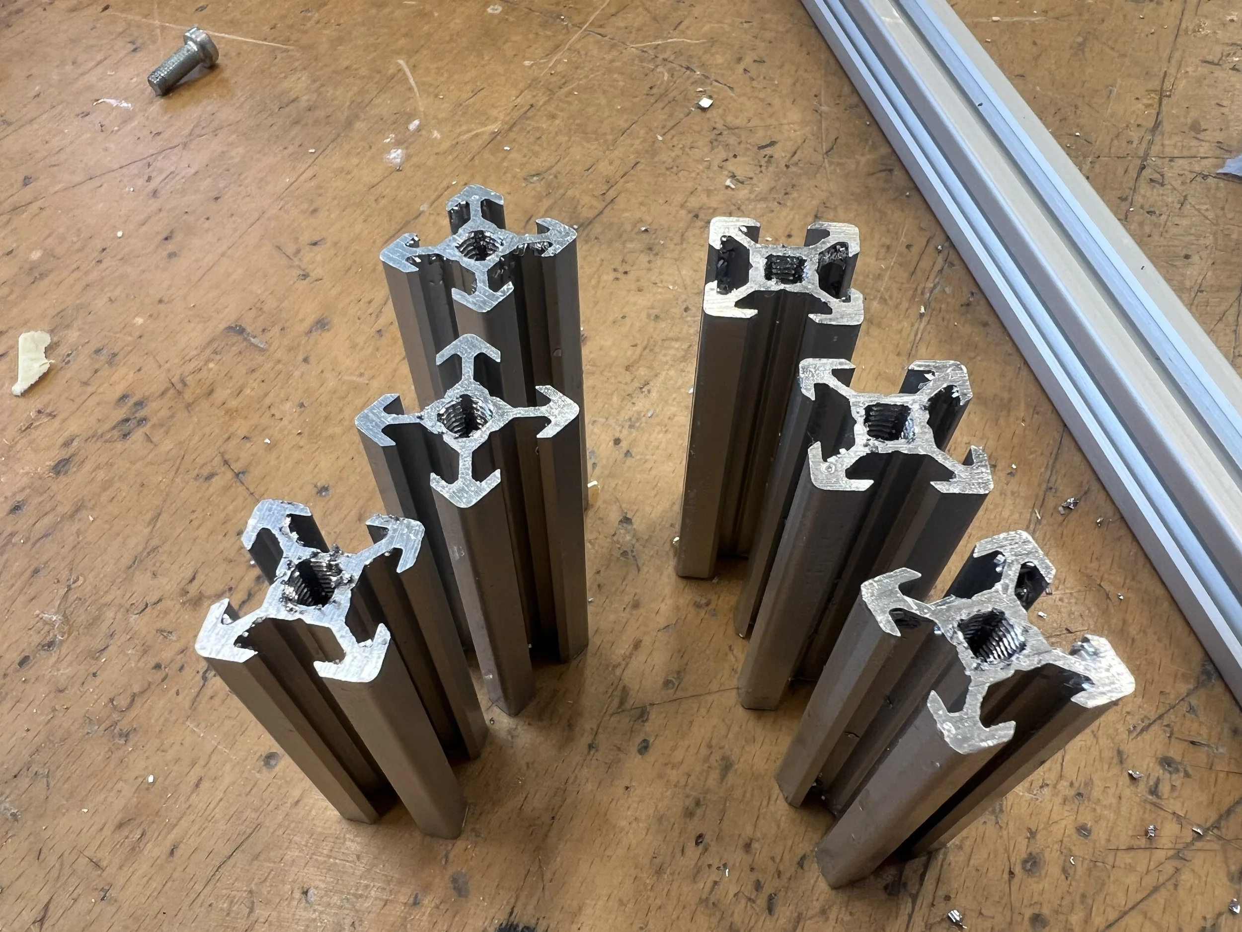
The remaining aluminum profiles were cut using a cross-cut saw and tapped accordingly.
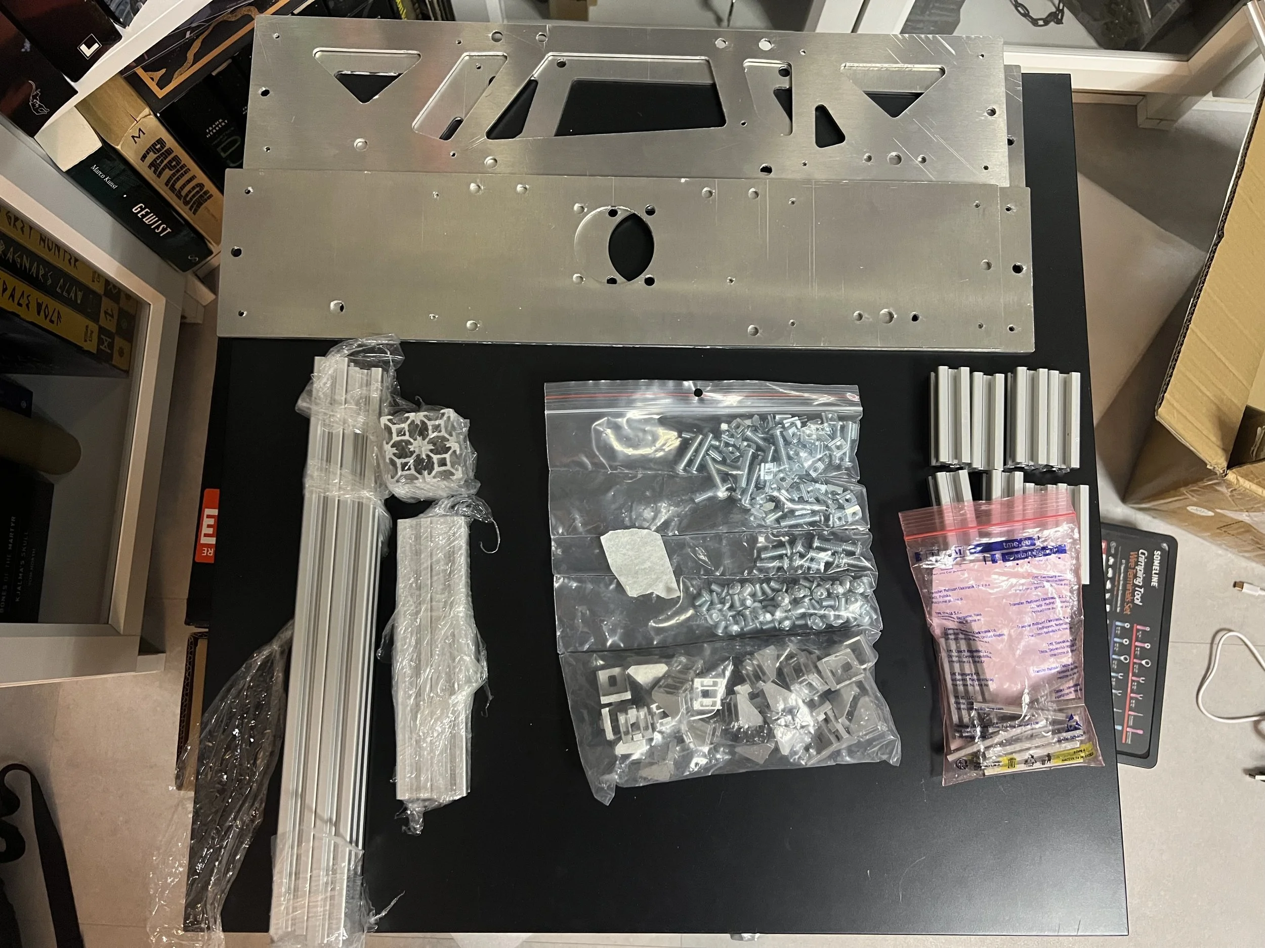
Once all the parts were manufactured or acquired the frame building could start.
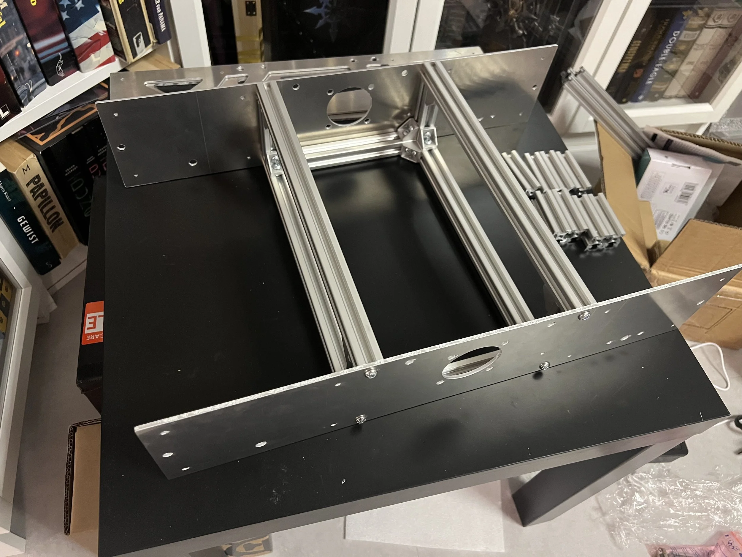
The frame basis was build and ready for the motors and drive system.
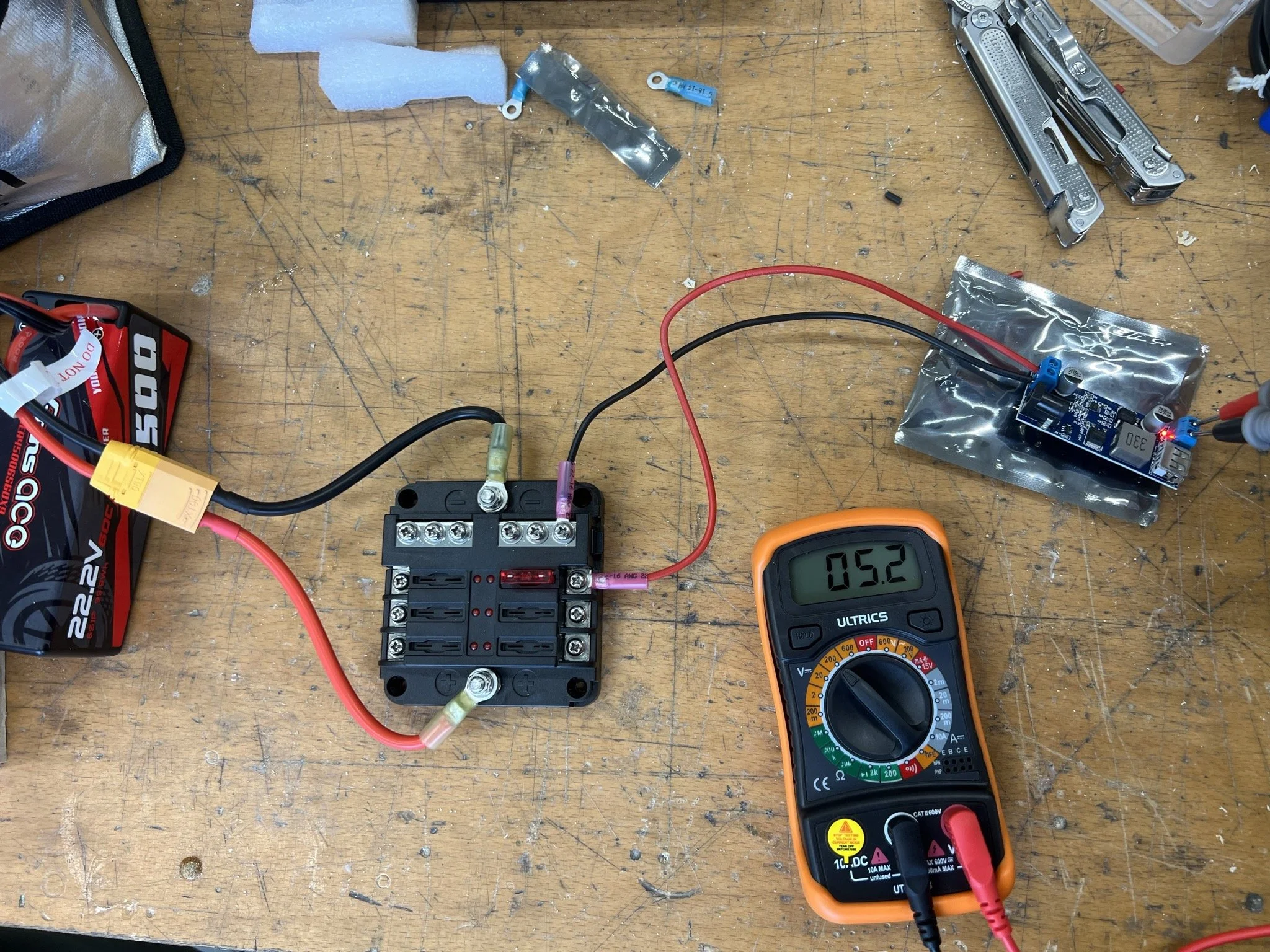
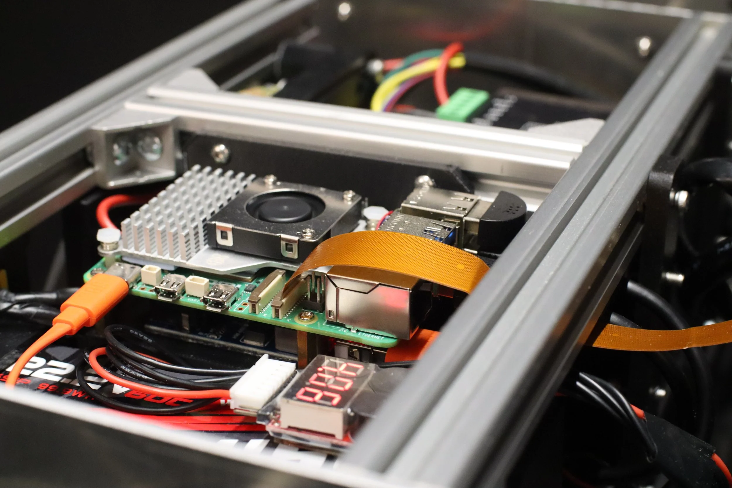
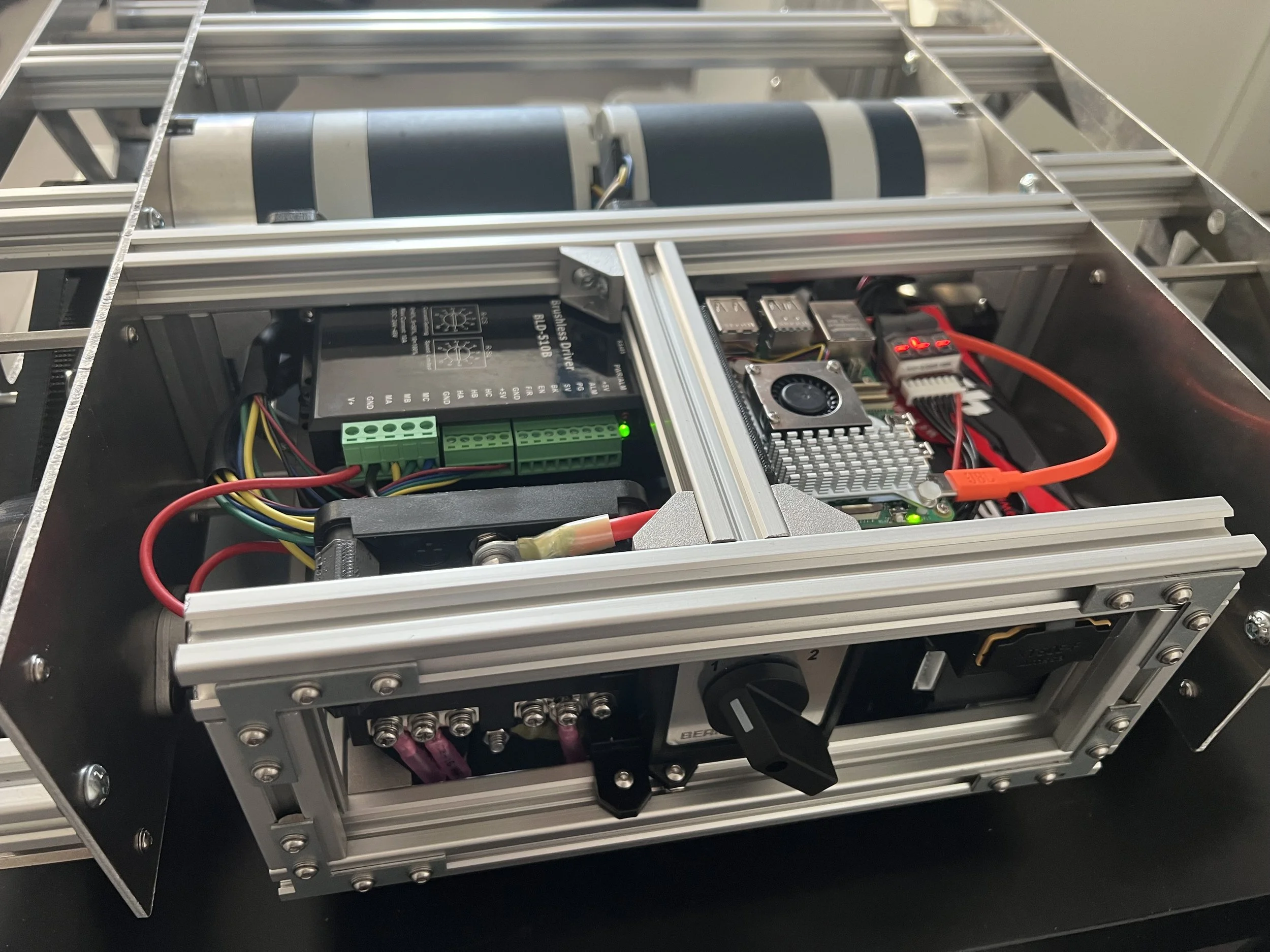
The electrical system is powered by a 24V LiPo battery and feeds a 5V Raspberry Pi 5 and the 24V motors. As such for safety a fusebox was implemented in combination with a step down converter.
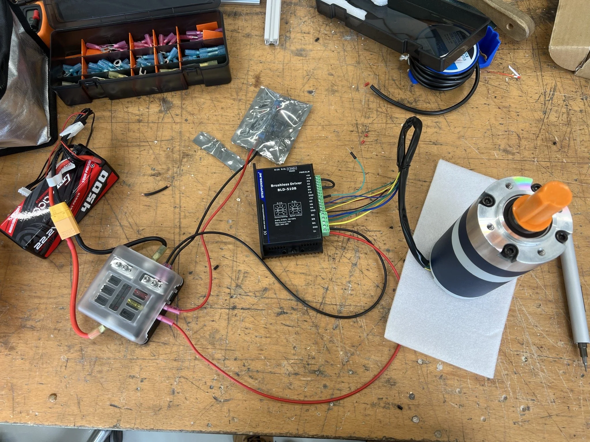
The motor controller and motor was connected to the system and the motor was successfully tested using simple motor controls.
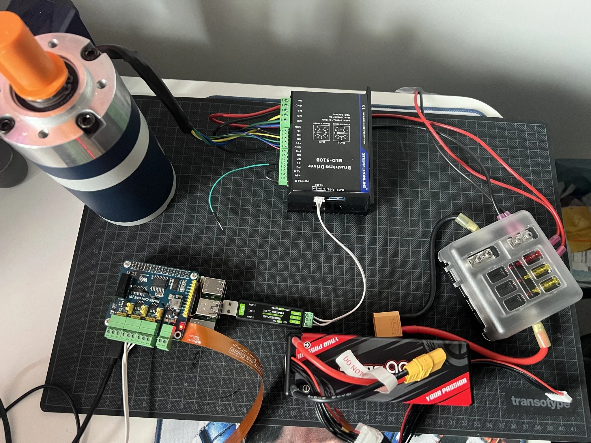
Subsequently the Raspberry Pi 5 was connected to the system and the first initial control code was created to move the motor.
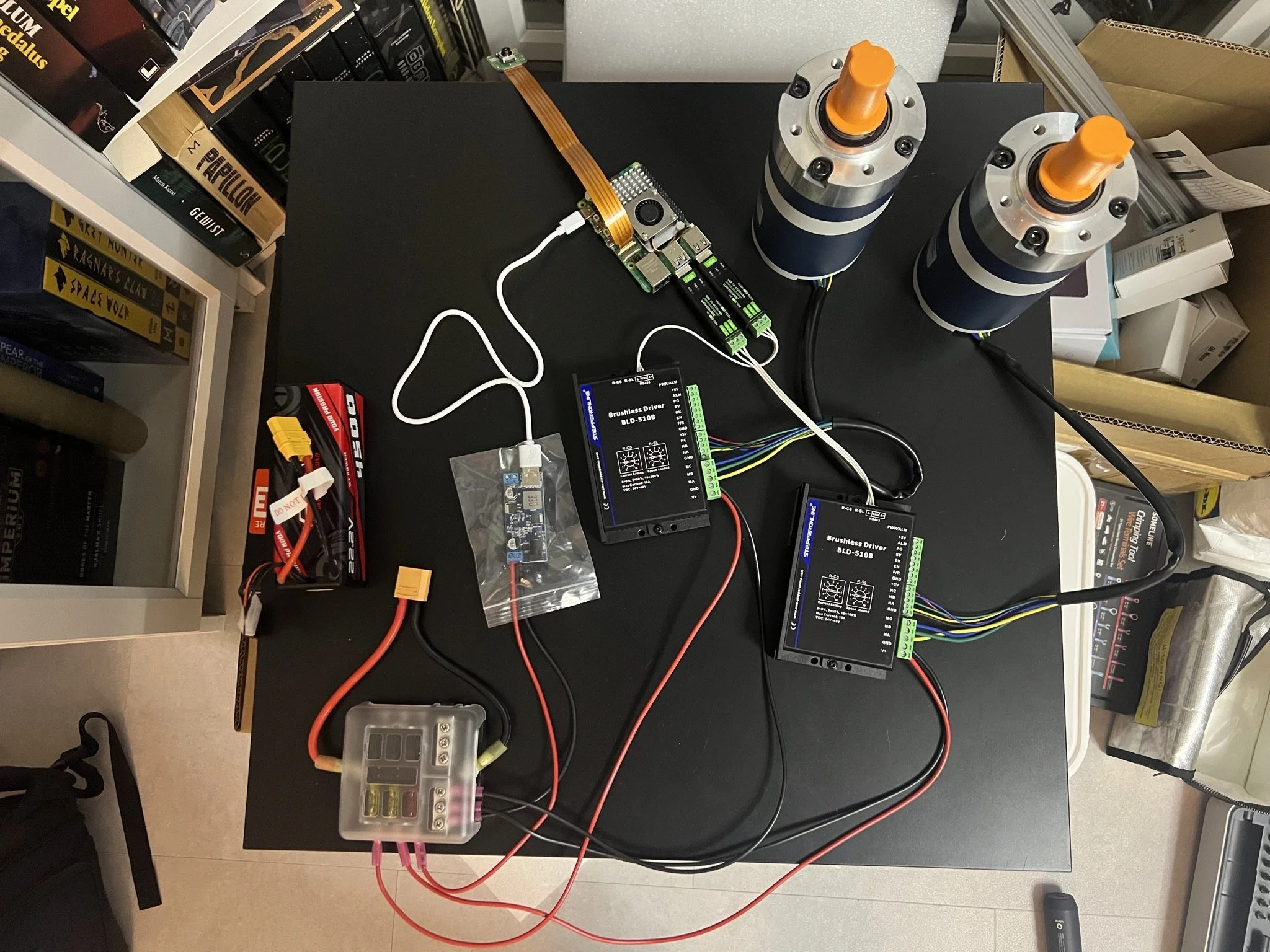
The setup was expanded to control both motors simultaneously.
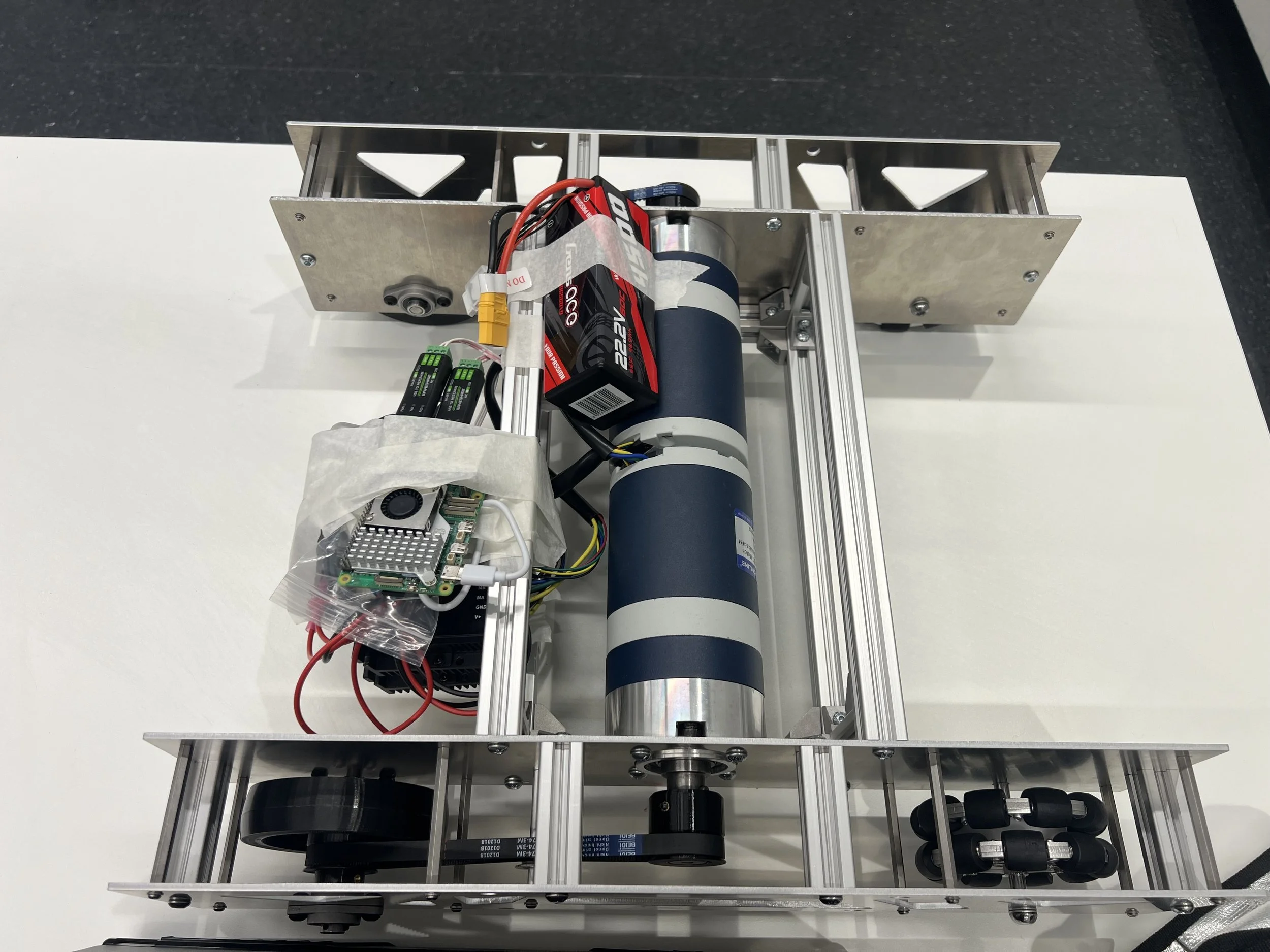
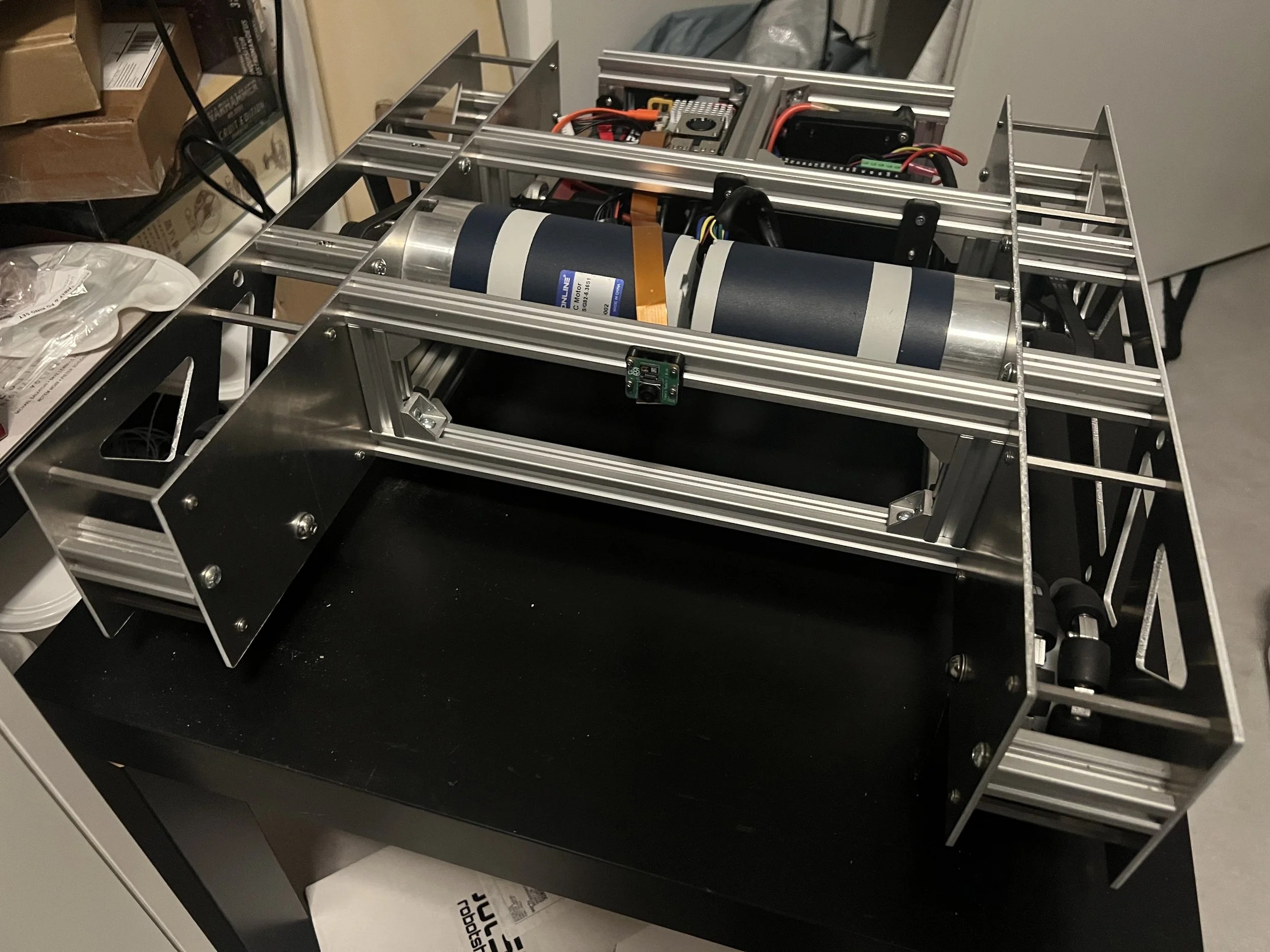
The motors were mounted to the frame for further testing.
The drive system was mounted and a stationary drive test was executed successfully.
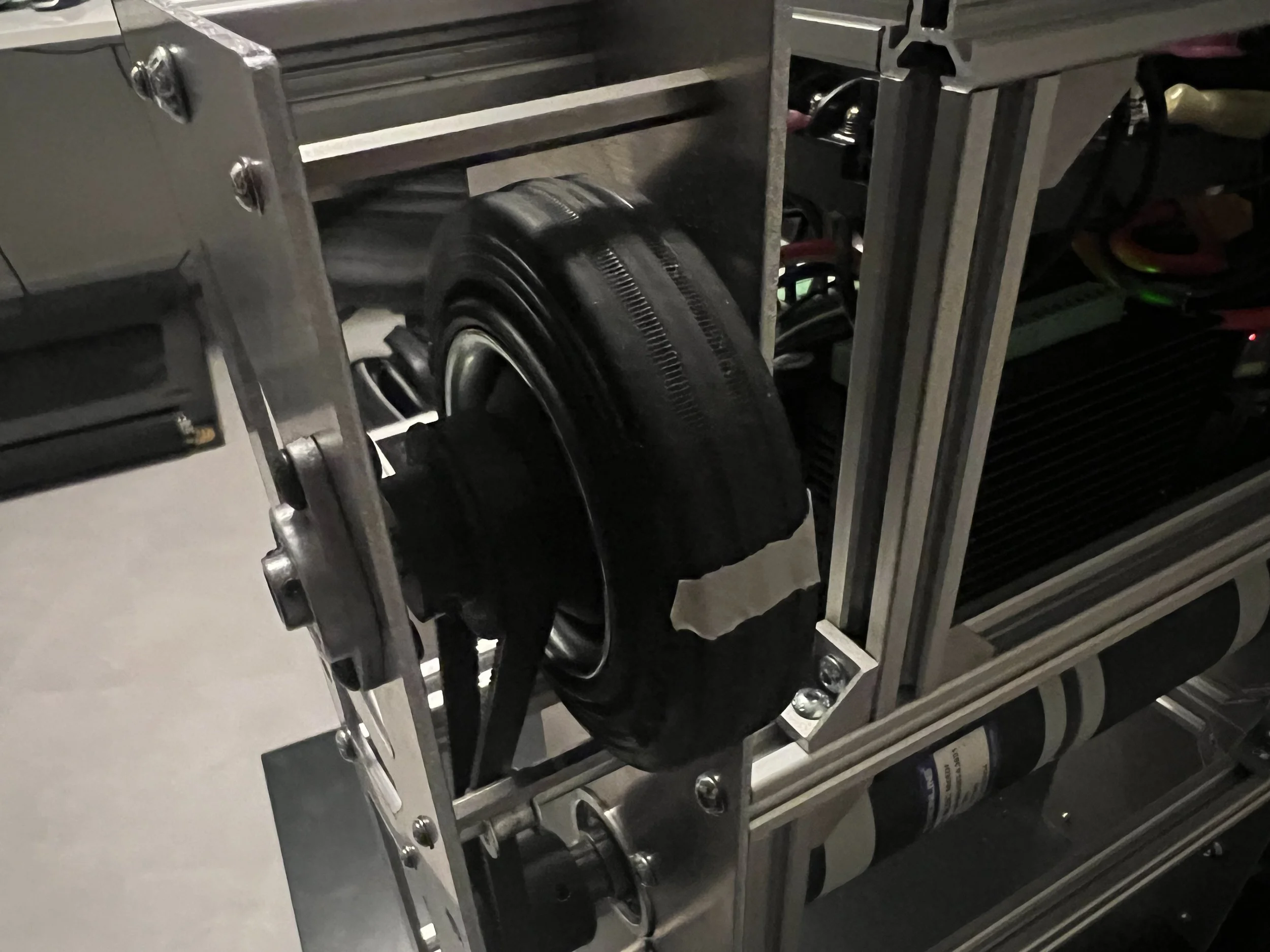
After successful stationary testing of the drive system, in combination with 3D printed drive wheels a first driving test was executed.
The driving test showed that the drive system works and the platform is ready for further iterations of control and fine-tuning.

Round 3: Integration
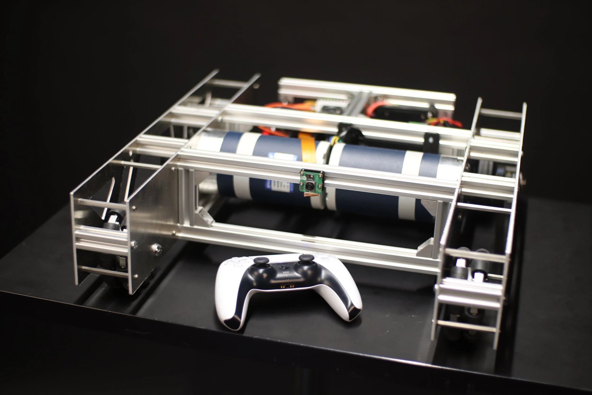
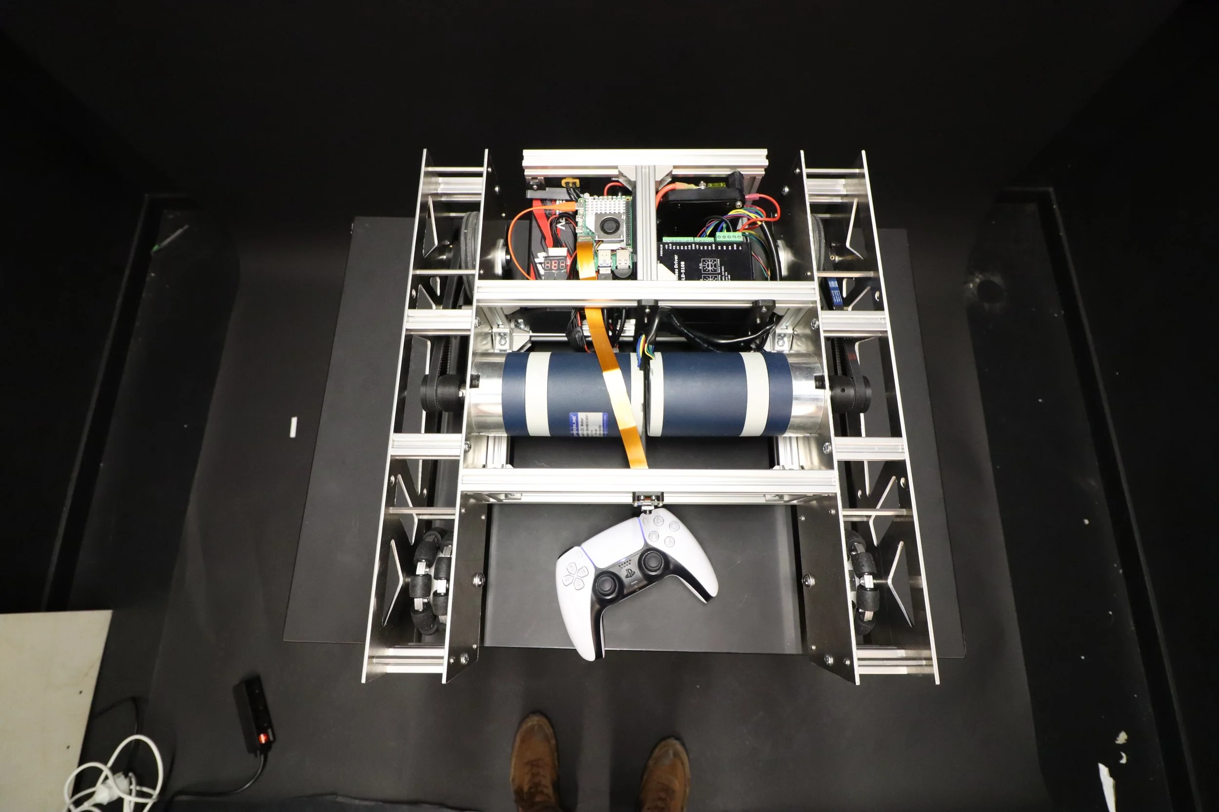
After successful integration of the drive system and Raspberry Pi, a controller was added for full remote control of the robotic platform.
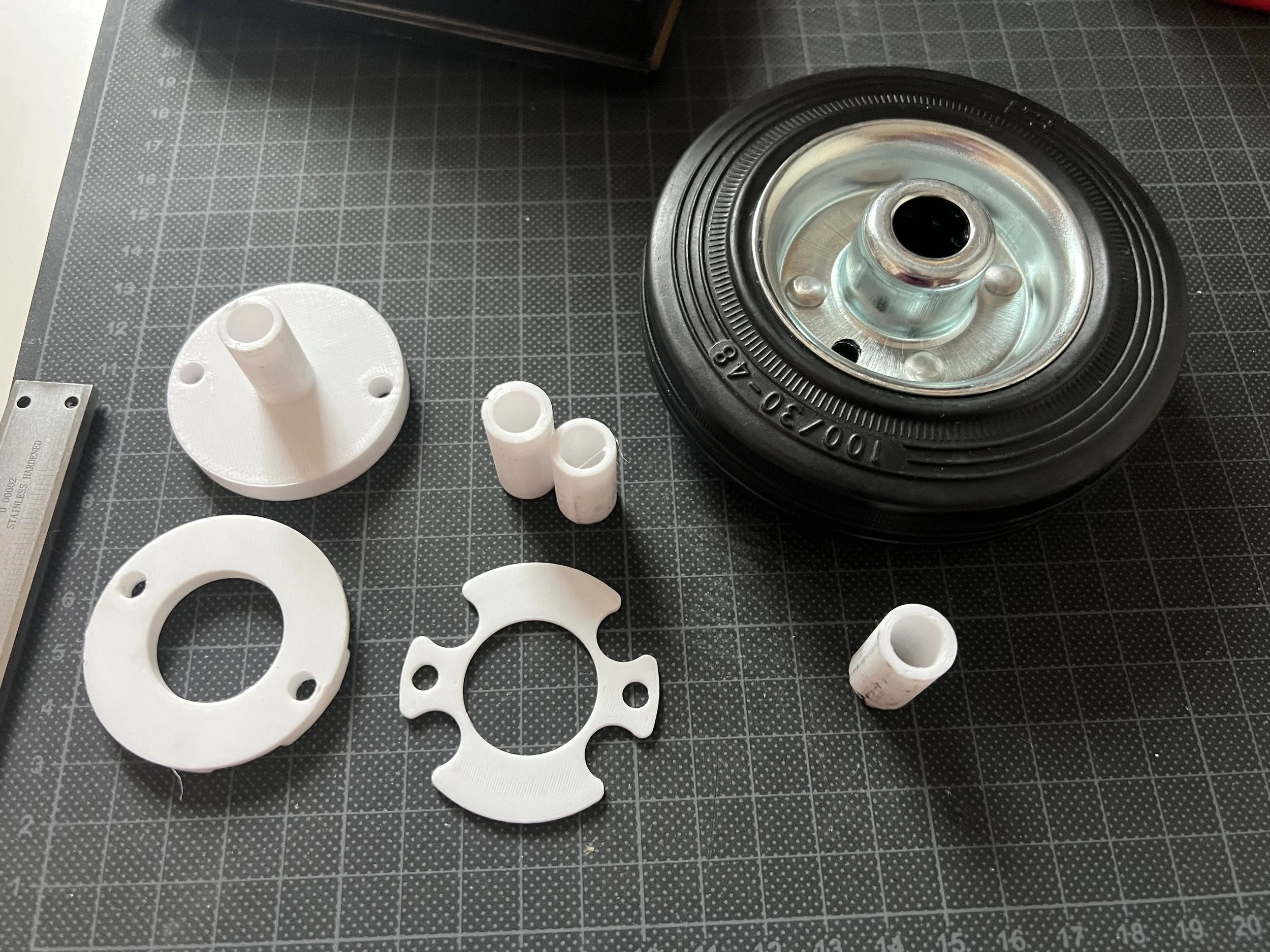
Due to an unforeseen part delivery failure, a new drive wheel type was acquired. This wheel had to be adapted for the design accordingly.
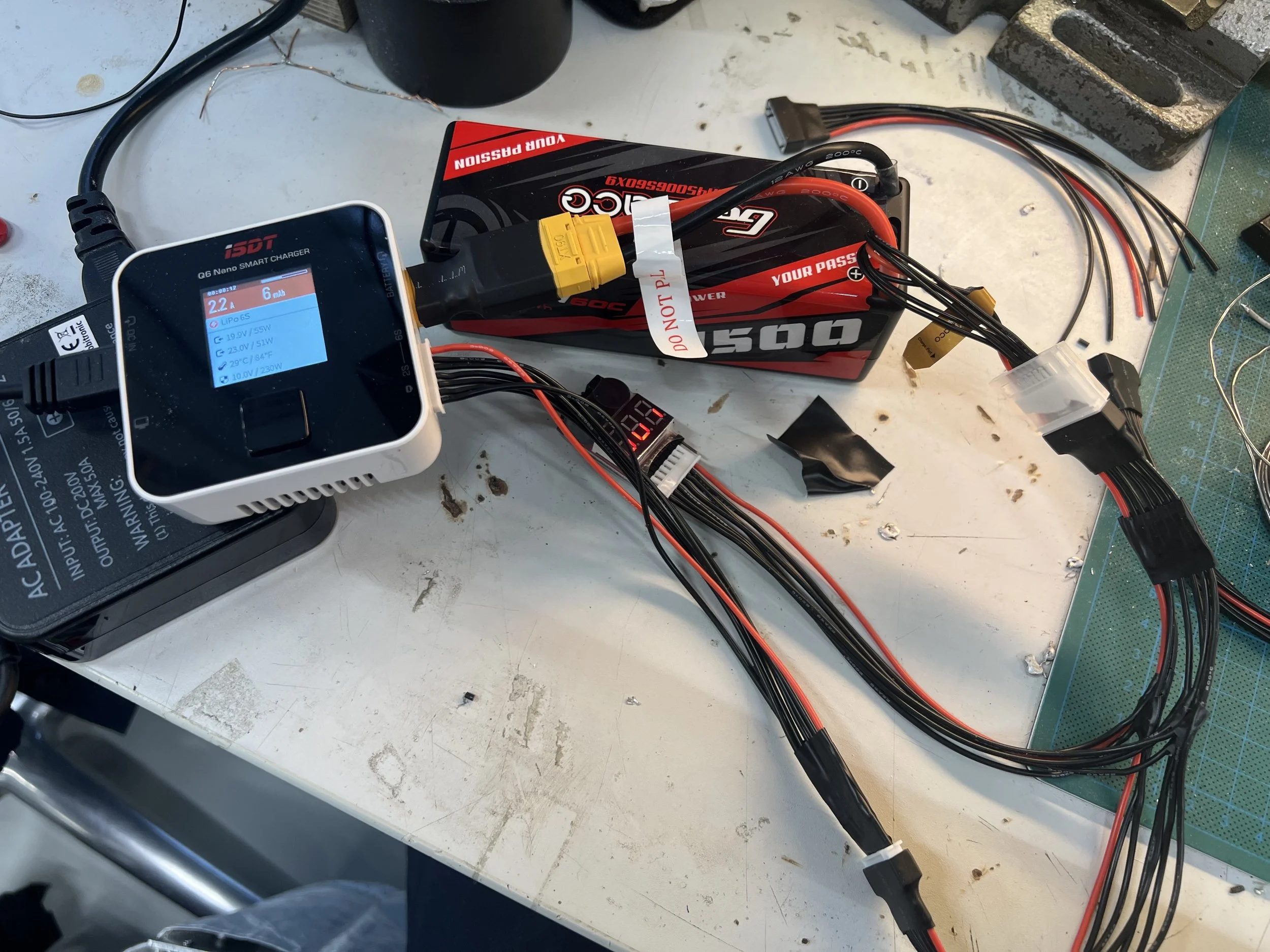
For better integration of the battery and charging. A custom wiring harness was created so the battery doesn't have to be removed for charging.
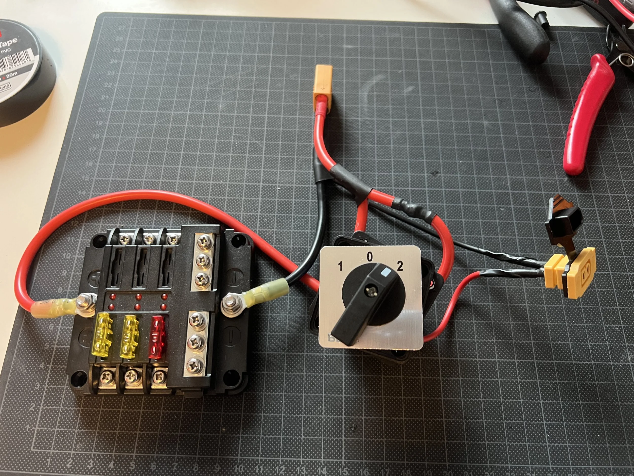
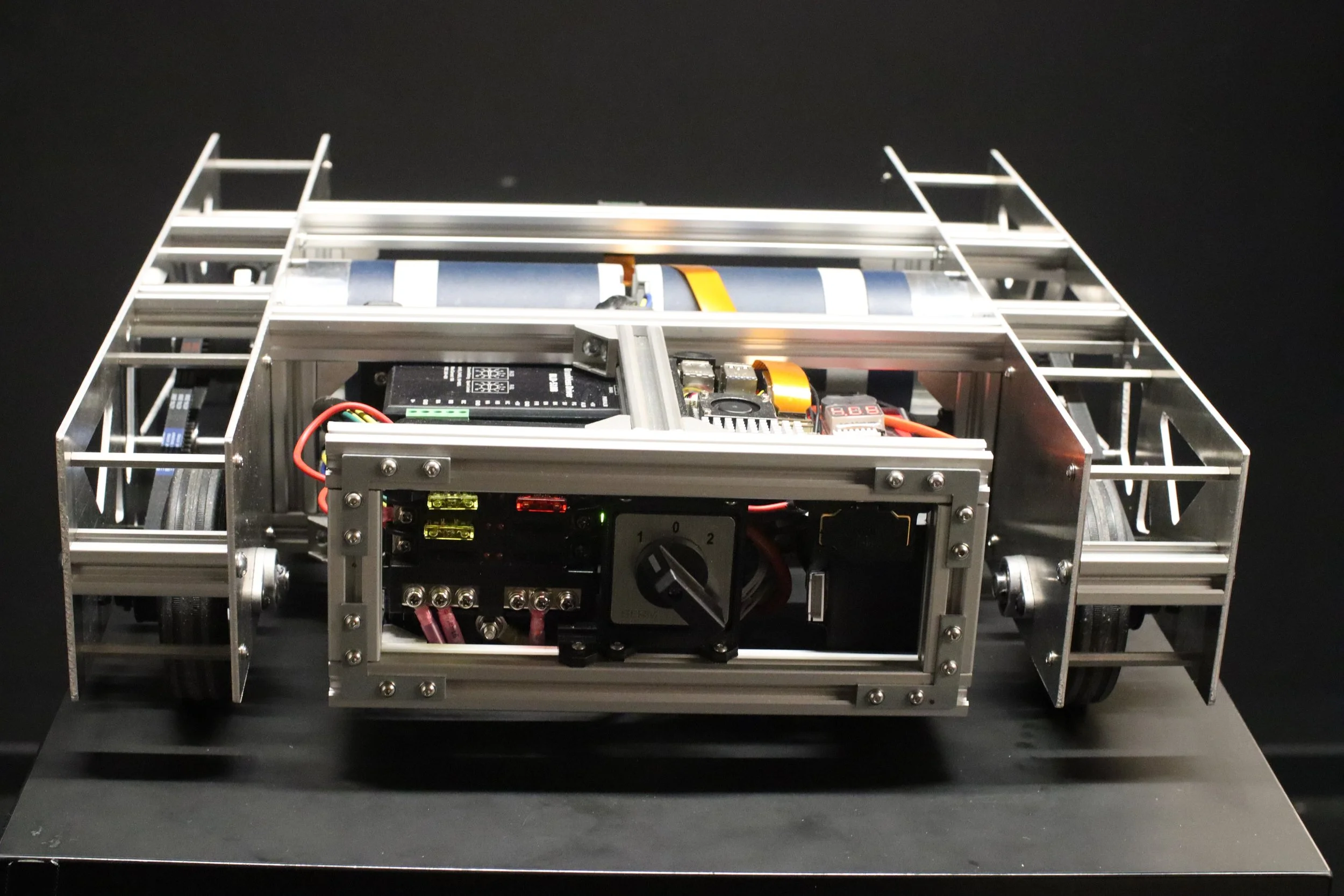
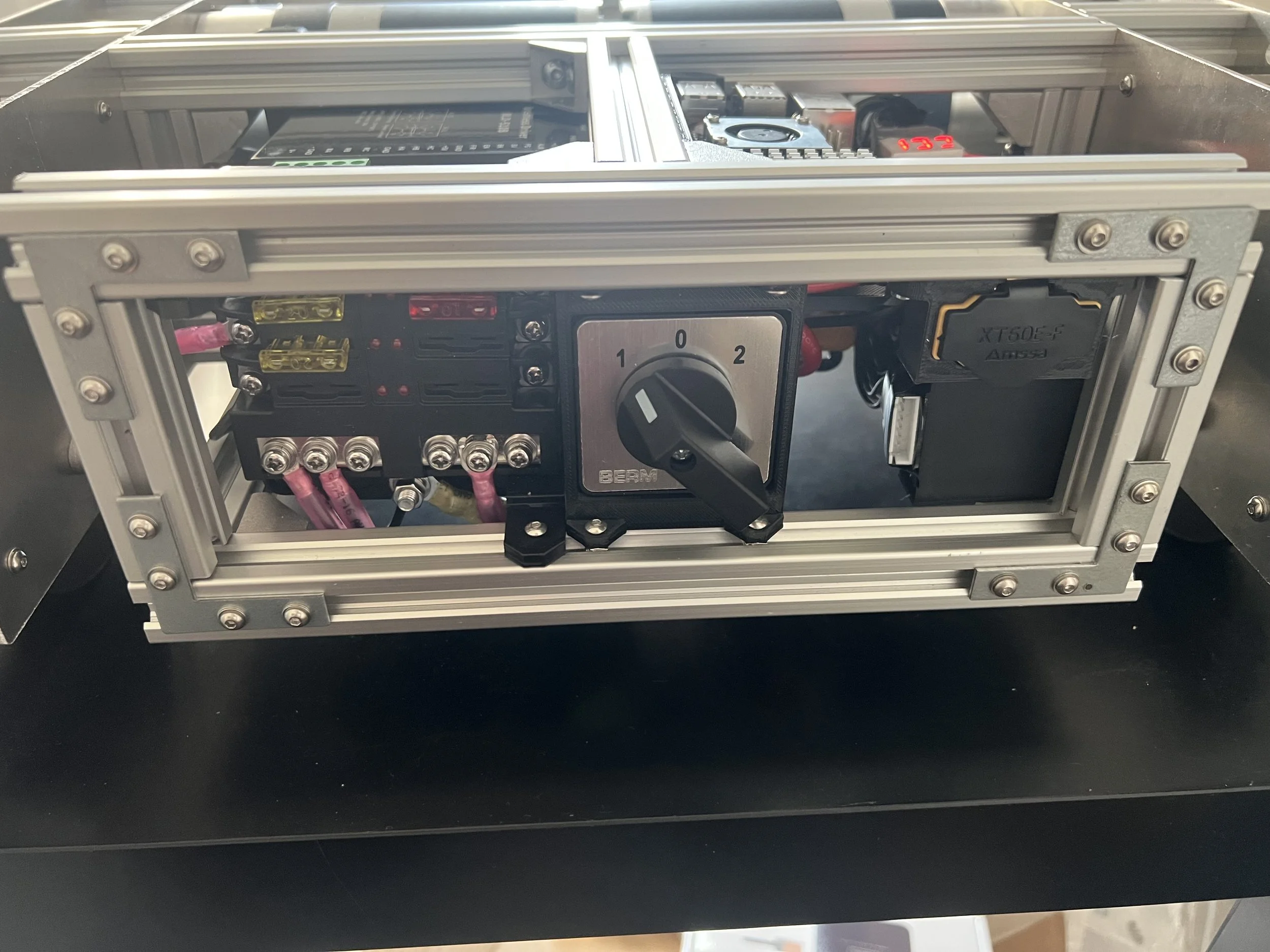
A rotating switch was integrated into the circuit to allow for on/off and charging/discharging states.
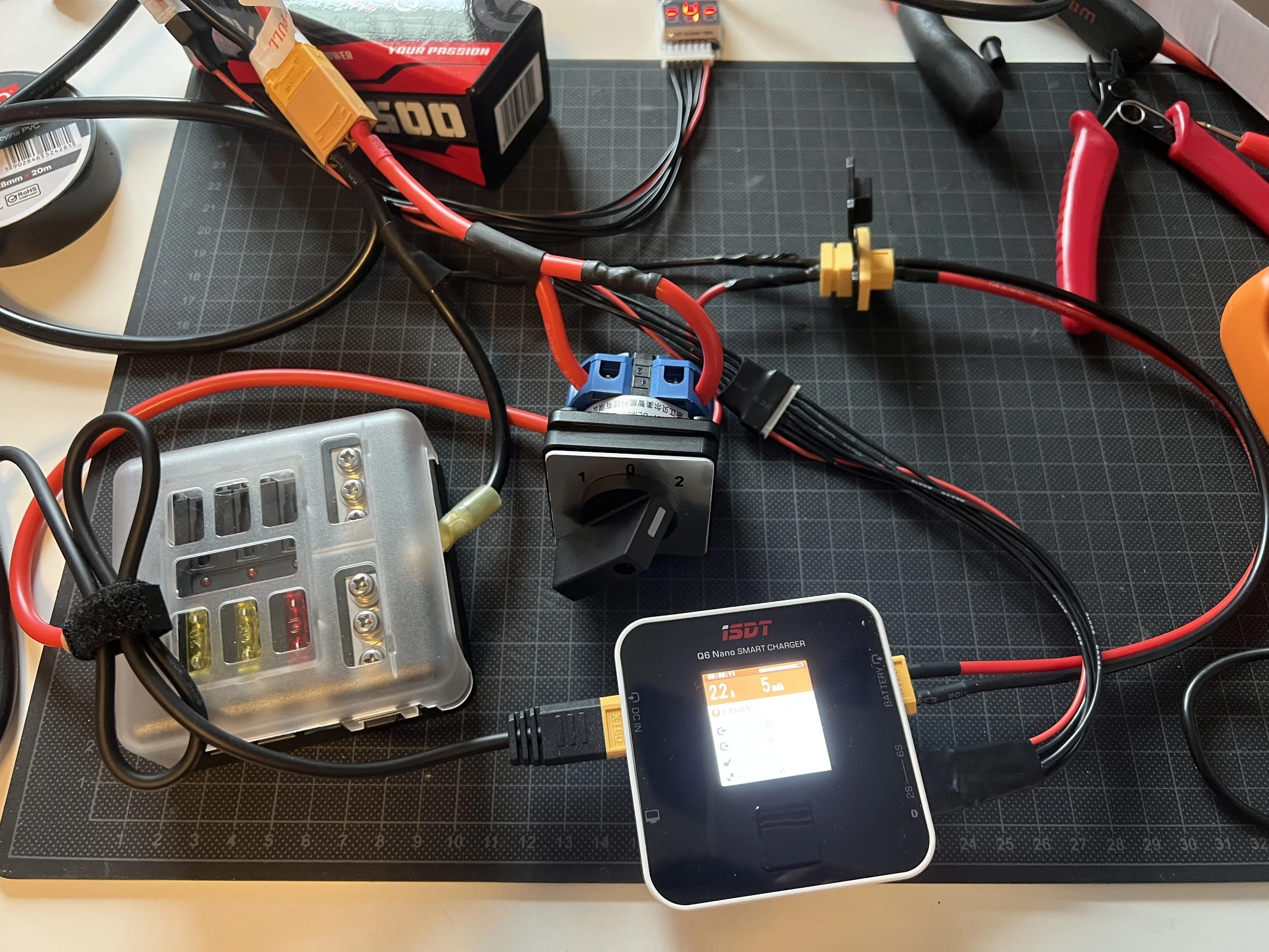
The new custom electrical circuit allows for an integrated charging solution and safety switch for the robot.
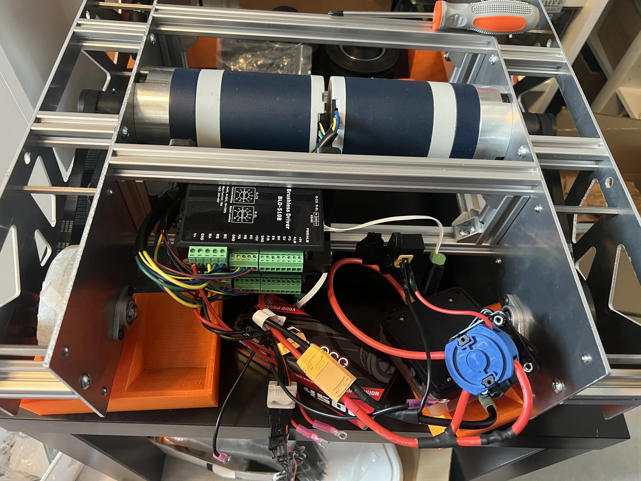
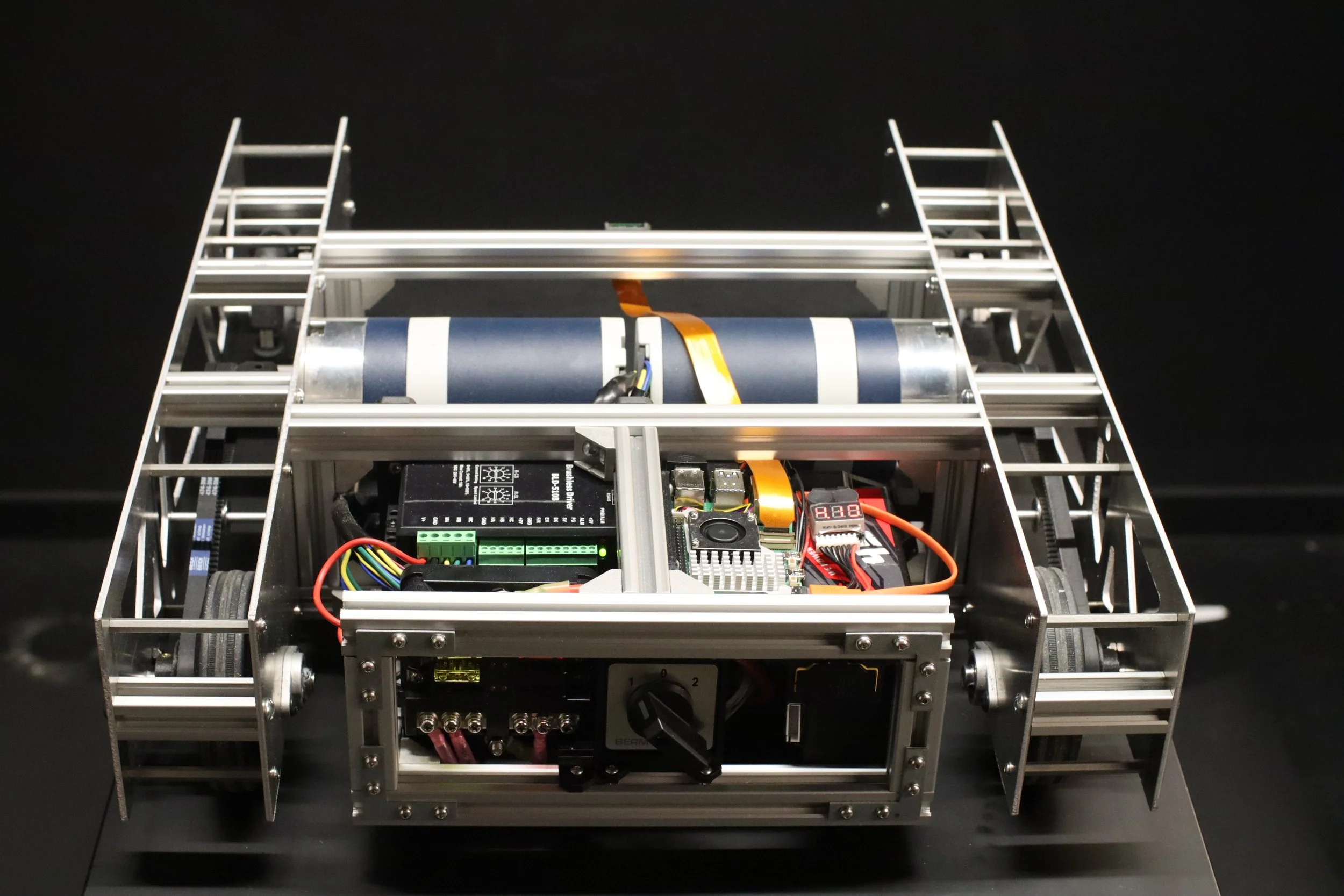
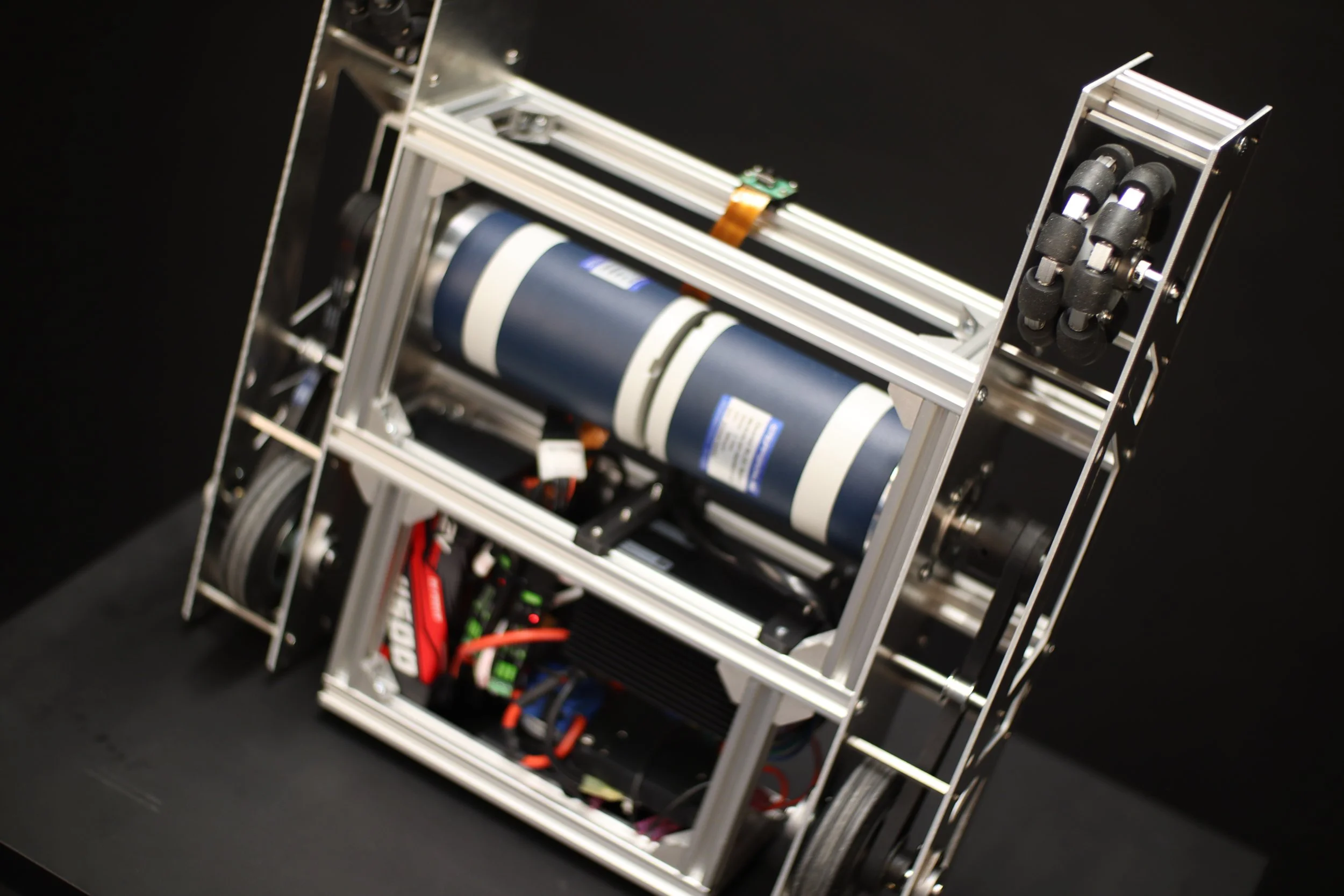
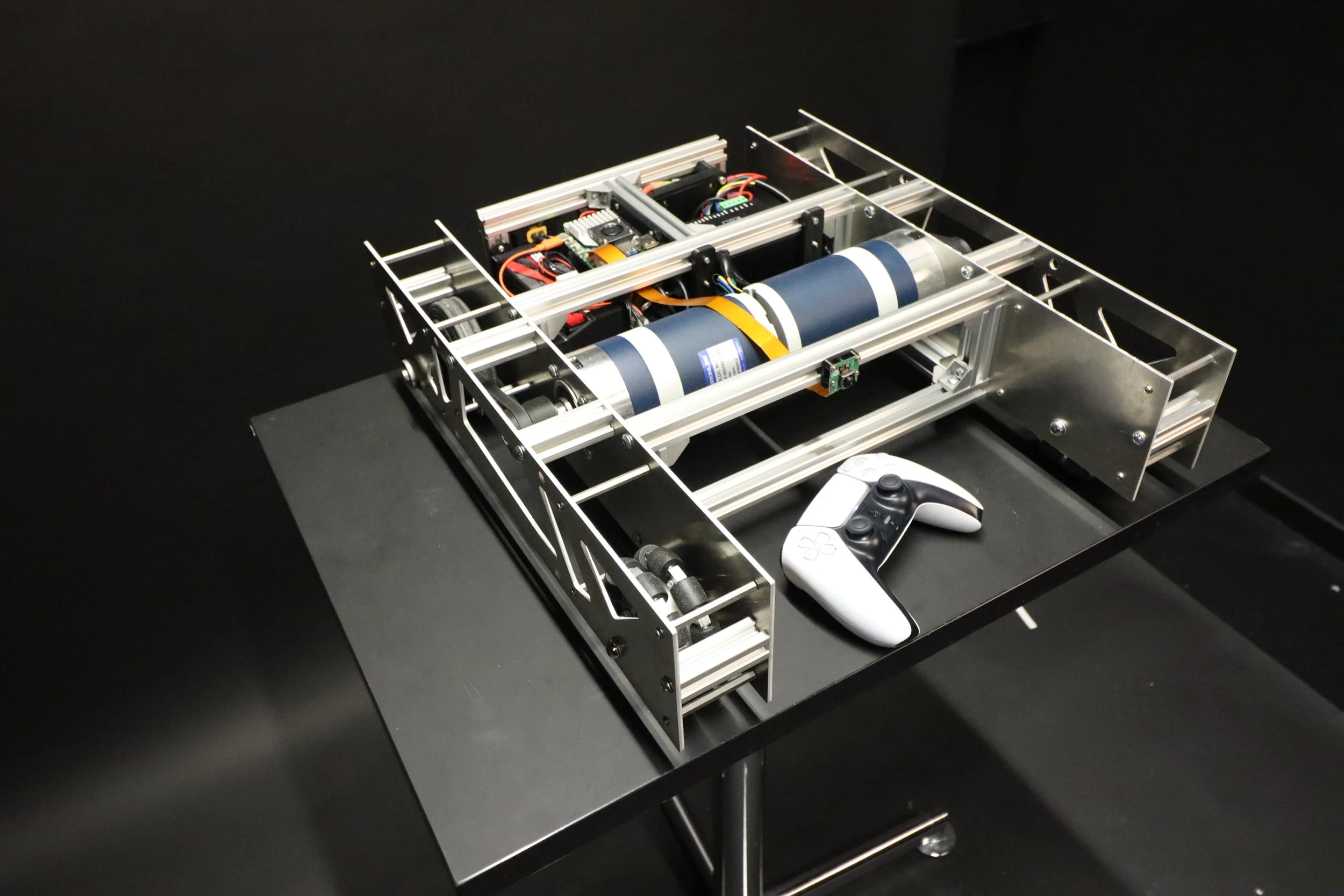
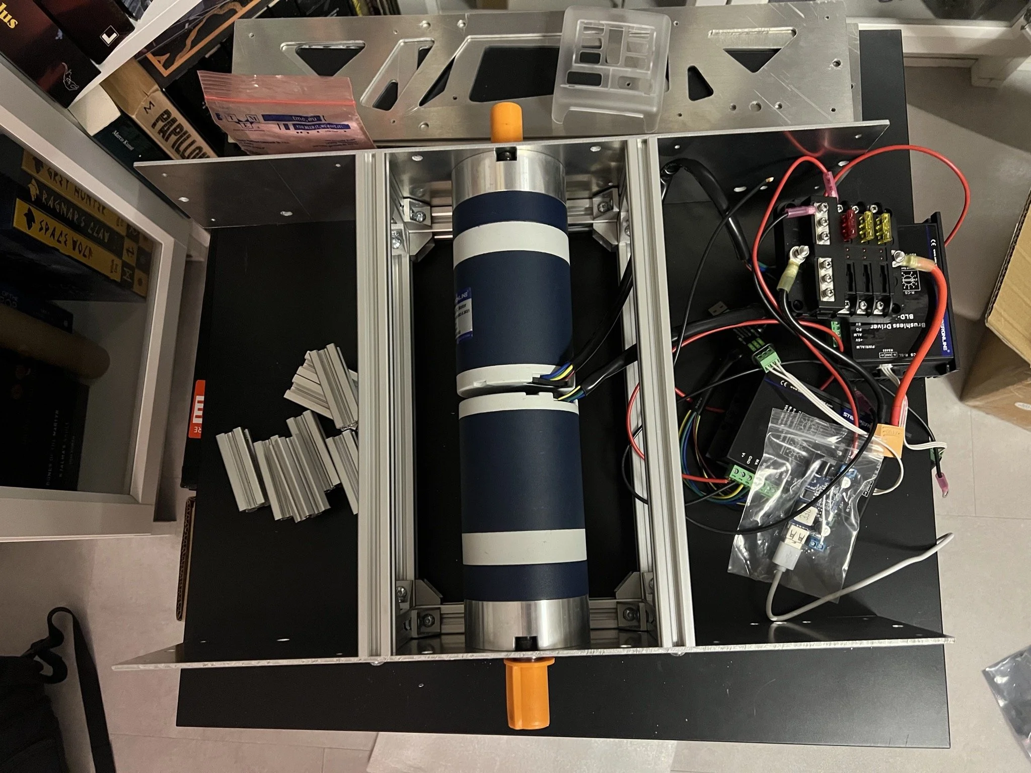
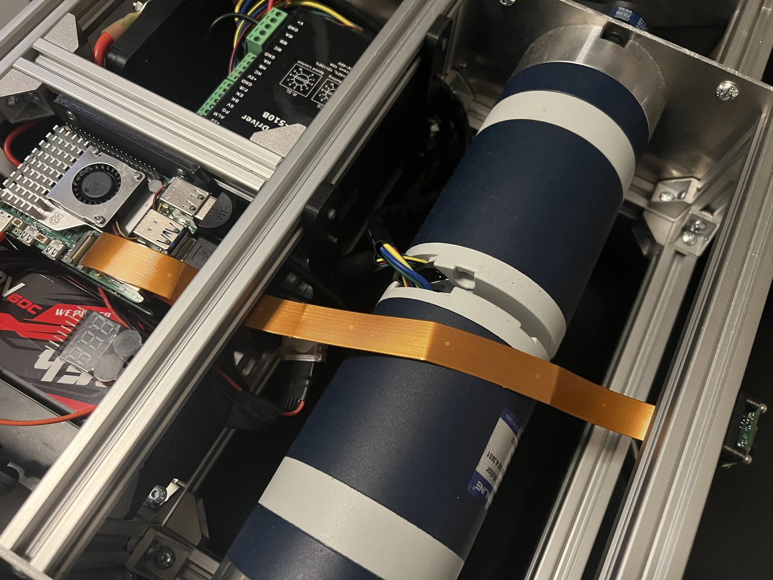
To integrate the electronics cleanly the components were positioned inside the frame.
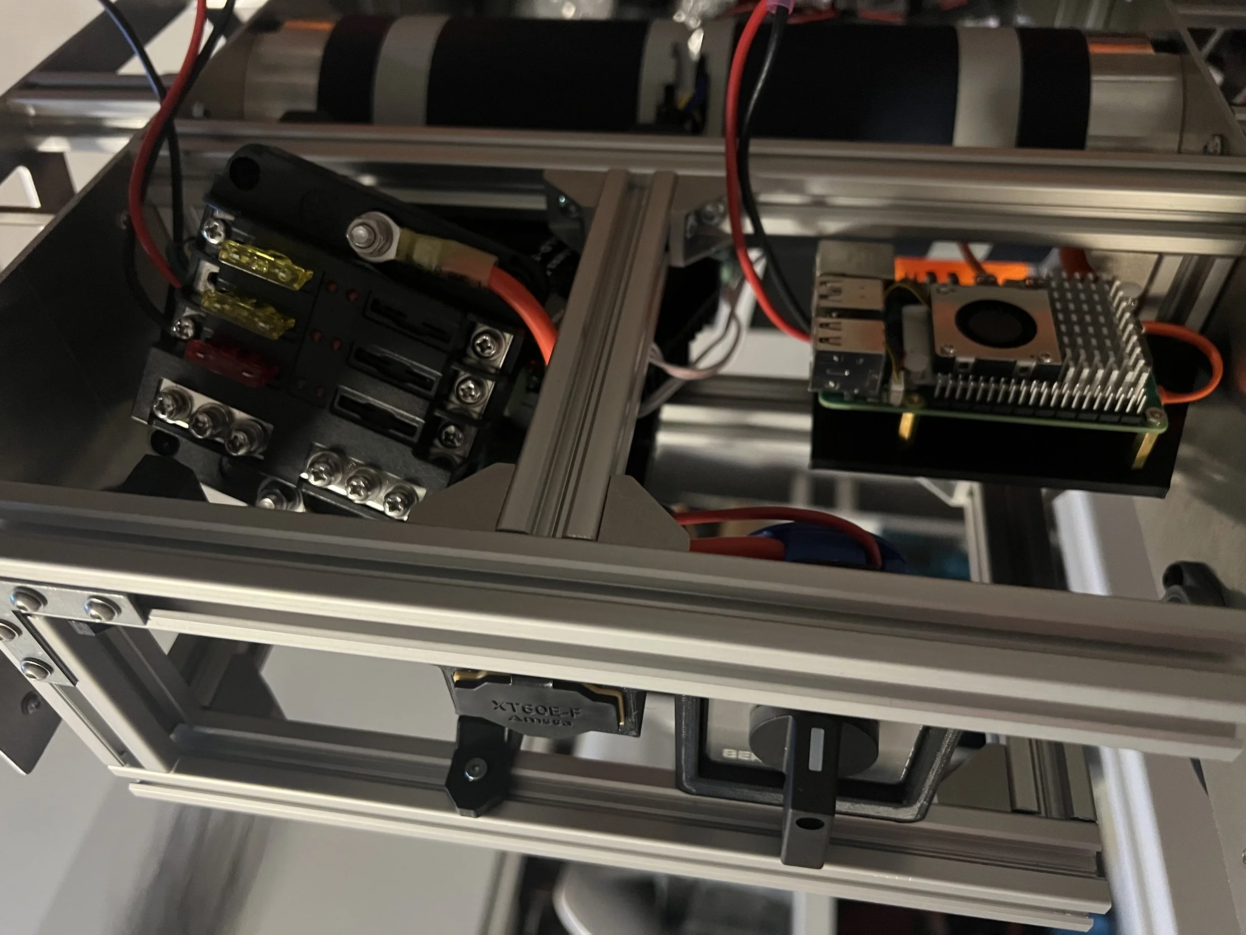
A frame was added to attach the components and mounts were created in SolidWorks and 3D printed.
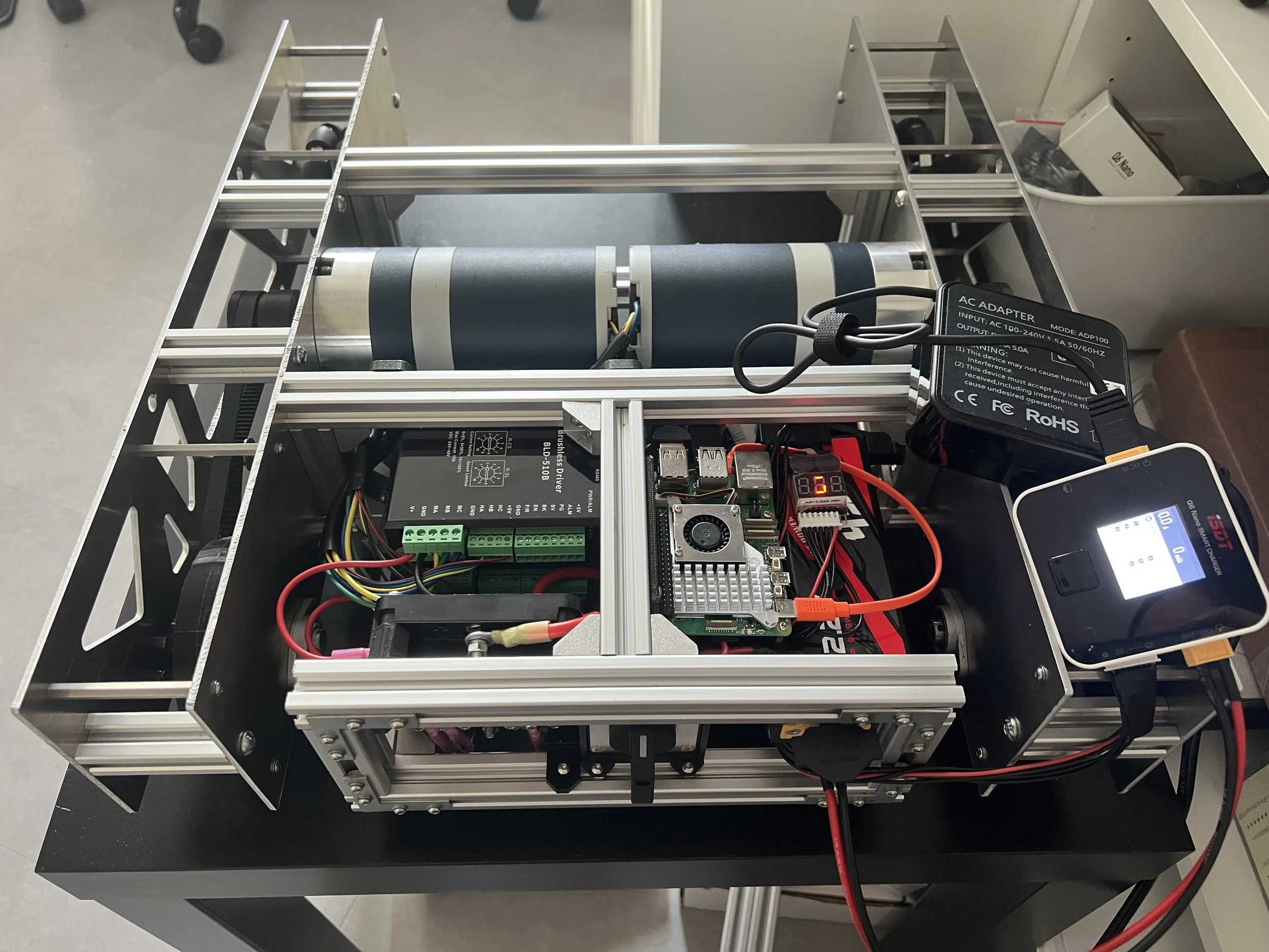
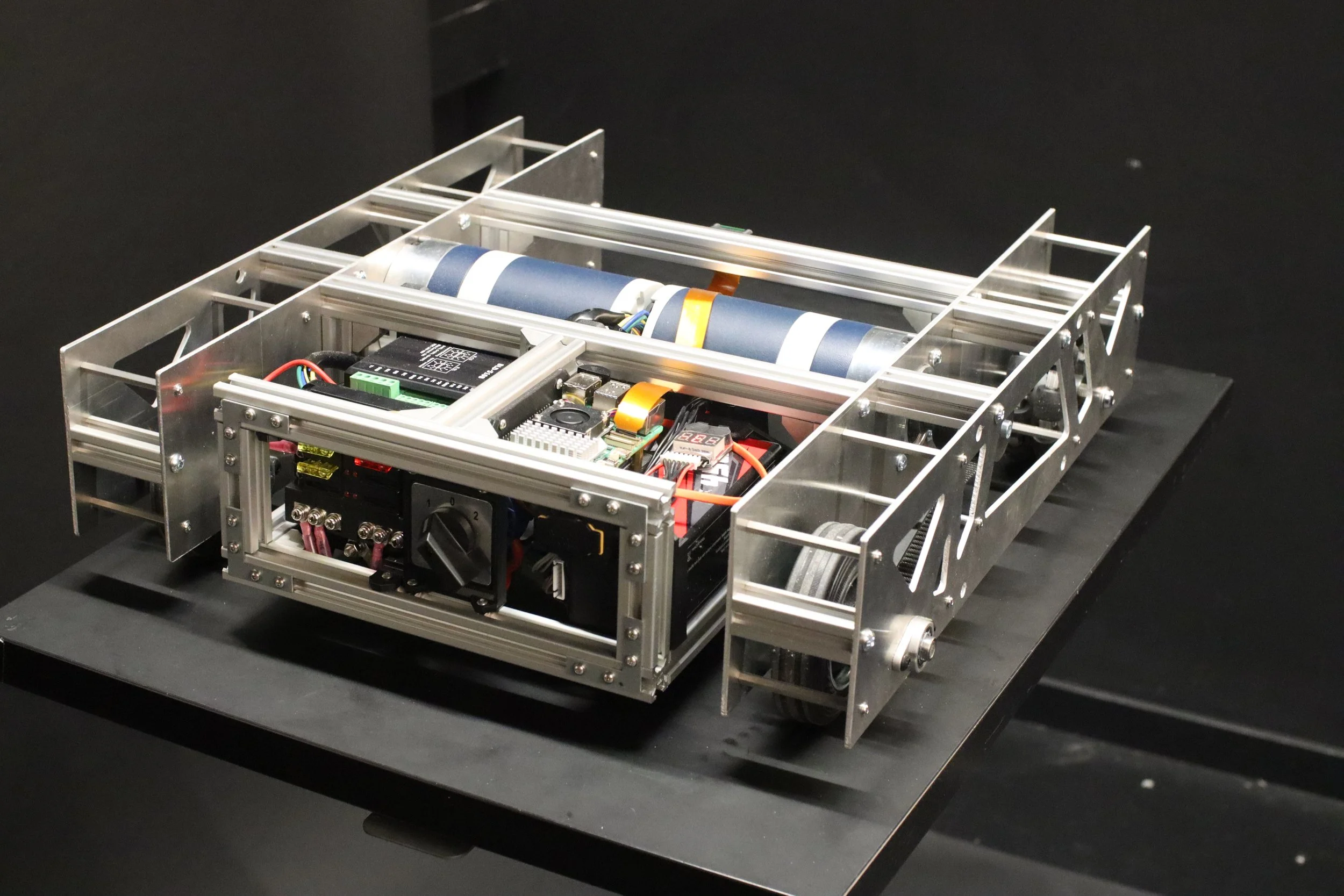
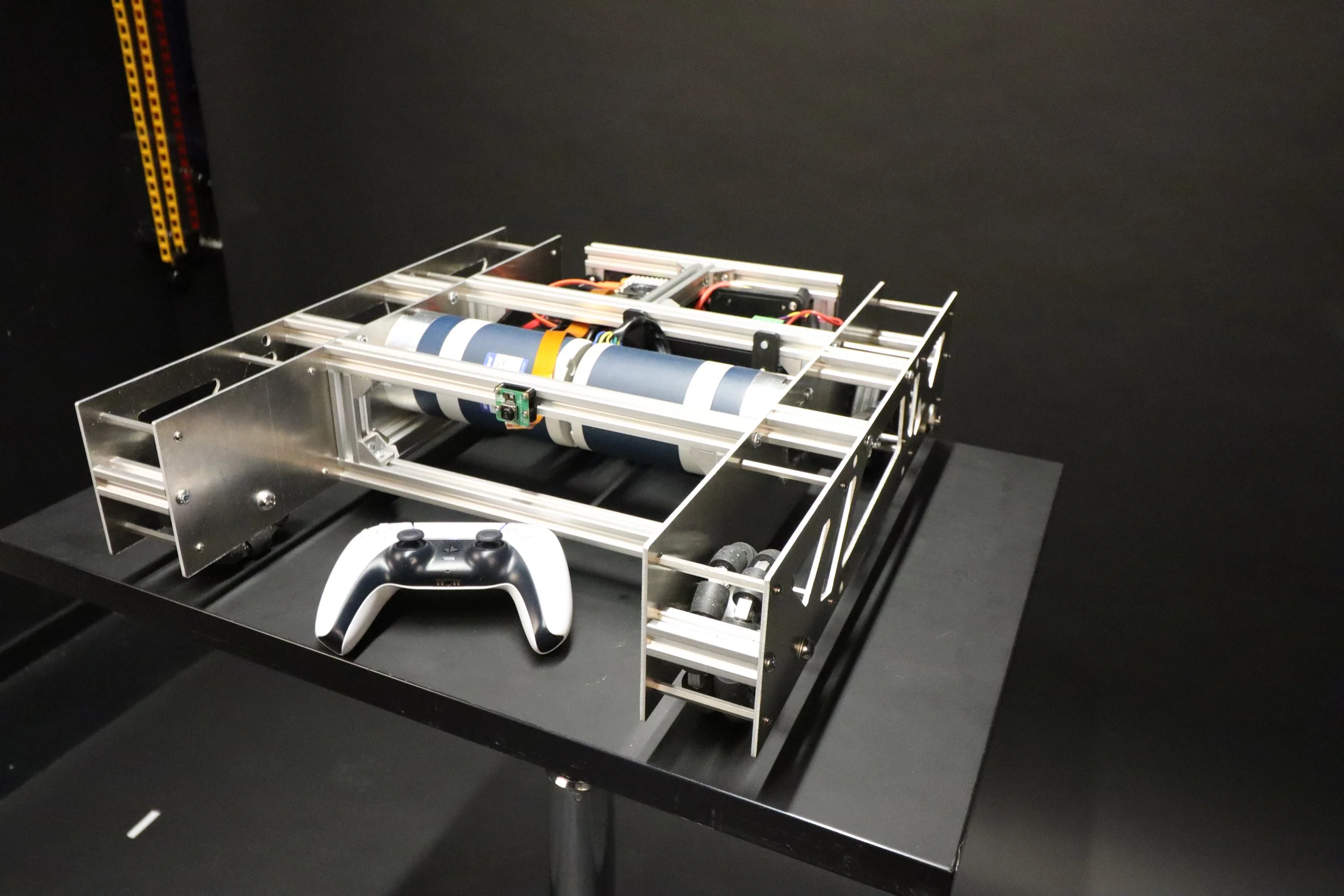
The resulting robotic platform is a fully integrated heavy payload system able to be expanded with the capabilities of the Raspberry Pi and its modular design.
Round 4: Iterate and Perfect
Using the feedback system of the motor controller and hardware-to-software translation the PID control was fine-tuned.
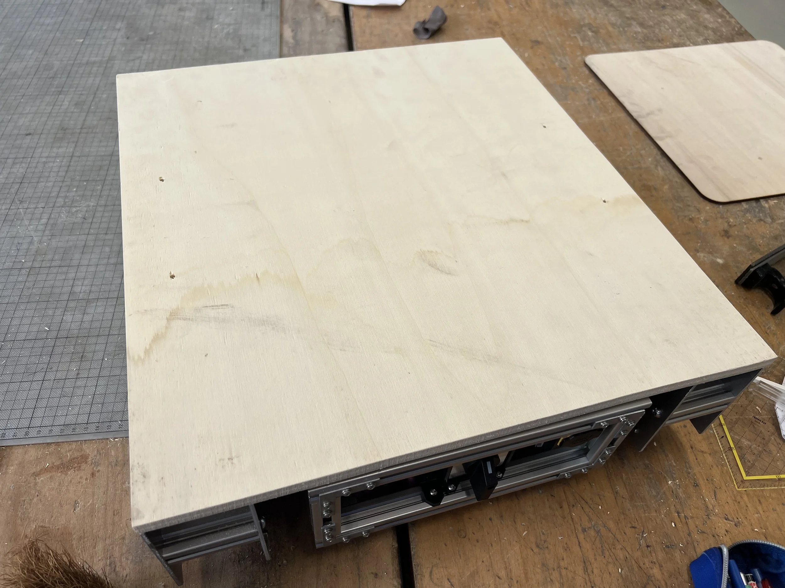
A wooden platform attached to the 2020 aluminum profiles adds a platform for carrying loads.
A camera was added to the robotic platform to allow for remote out-of-sight control.
Finally some real world testing was done for the final result.

Final Result
I present Atlas Prime: A modular robotic platform with endless possibilities.